Leading Manufacturer of Underground High Voltage Cable in China
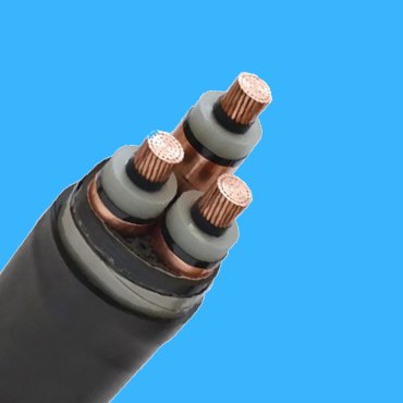
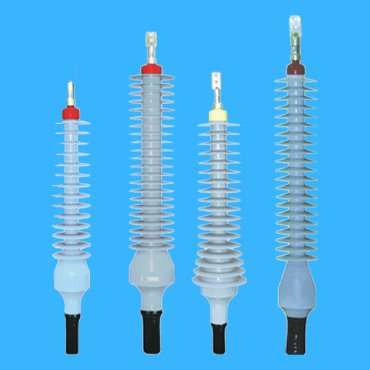
Being a leading manufacturer of this underground high voltage power cable over 20 years, we are able to offer you a complete range of power cables up to 500kV, together with its cable joints, cable joint box or cable termination.
What is an Underground High Voltage Power Cable
Referring to AEIC standard, it has five main voltage levels for this high voltage power cable; they are 69kV, 115kV,138kV,230kV and 345/400kV; Referring to IEC standard, it has six types underground power cable; they are 40/69kV,64/110kV,76/132kV,127/220kV,230/400kV,290/500kV.
We understand, this underground high voltage power cable has a complicated structure and design; Our expert engineers are able to give you a quick response to your endless technical questions and propose a perfect cable design to your custom fit; Please feel free to cotact us for your specific requirement of this underground power cable.
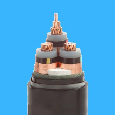
Underground High Voltage Cable by IEC Standard
Referring to IEC 60840
Stranded Cu or Al wires to BS 6360
XLPE Insulated & Sheathed by PE
Solid, Stranded or Segment Conductor on your options
Conductor shielded by a semi-conducting material
Metallic shielded by Cu tape or wires
Insulated by XLPE & Shielded by a semi-conducting material
Outersheath by PE with an Al tape
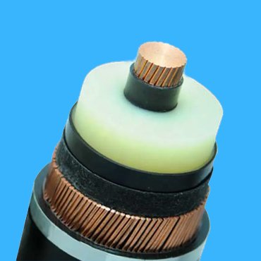
Conductor range from 240 to 2500mm2
Standard refer to IEC 62067
Triple Extrusion of CS,Insulation & IS
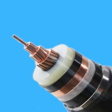
XLPE Insulated Power Cable
Metallic Layer by Cu tape or wires
Outer Sheathed by PE with an Al tape
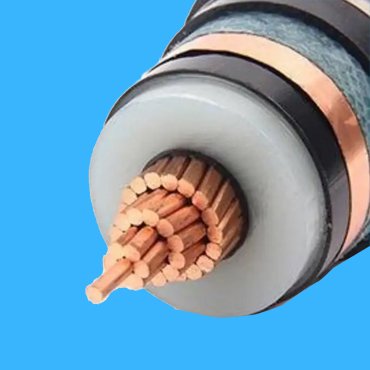
Reffering to IEC 62067
Waterproof material used between IS & Metallic layer
Al or Cu conductor from 800 to 2500mm2
Underground High Voltage Cable by AEIC Standard
Product Feature Box


World Leading Manufacturer for Underground High Voltage Cable
We are one of the top producers of high and extra high voltage energy cables in the world. We manufacture a wide range of underground high voltage cables up to 500 kV. Additionally, we provide services such as cable laying, jointing, termination, testing, on-site supervision, and final commissioning, as well as turnkey project contracting for underground high voltage cable infrastructure.
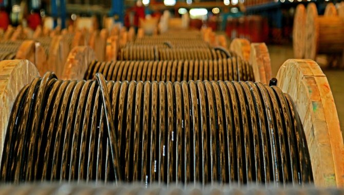
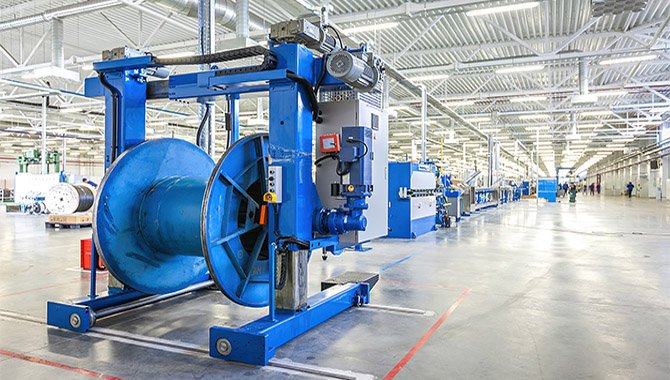
State of the Art Manufacturing Facility
Our State of the Art Manufacturing Facility, established in 1995, has a total area of 500,000 m2 (outdoor area) and 80,000 m2 (closed area). It consists of a Cable Factory and a cable accessory factory that produces underground high voltage cables and accessories up to 500 kV. Three High Technology CDCC production Lines and in-house a Test Laboratory are in operation in it.
Excellent Cable Reel Management
A quality cable reel management system ensures that all cables are kept safe and secure throughout the shipping process, making it easy for you to install underground high voltage cables.

Cable Passed Type & Prequalification Tests Conducted by KEMA, CESI


Our production capacity for cables is up to 3,000 km per year, depending on exact type of underground power cable. As of 2020, we have produced and shipped more than 20,000 kilometres of high voltage and extra high voltage underground power cables, some of which has passed type and prequalification tests conducted by KEMA, CESI and other testing institutes. Started from 2020, we launched our package solutions for Power transmission & distribution lines and new energy projects from underground power cable to its cable accessory, technical consulting, design & installation, final commissioning and on-site technical support.
Related Product
Grounding methods for underground high voltage cables
The electrical safety regulations stipulate that all non-charged metal shells of electrical equipment must be grounded, so the aluminum cladding or metal shielding layer of the cable must be grounded. Usually, cables with voltage levels of 35kV and below are grounded at both ends. The reason is that most of these high voltage cables are in three aluminum or copper conductors. In daily operation, the total current transmission through the conductors is zero, so at this circumstance, there will be no magnetic field occured around the conductors ans its metal shielding layer. Therefore, there is no induced voltage aroused at both ends of the conductors or the shielding layer, so accordingly there will be no induced current transmission after grounding at both ends. However, when the cable voltage over 35kV, most underground power cables are in a single conductor. it will be changed accordingly. When the conductor of this underground high voltage cable passes through an electric current, there will be a magnetic field wire cross-linked with aluminum or metal shielding layer, causing induced voltage to appear at both ends. it will caused induced voltage and current aroused at same time, and will heat the cable,due to its fixed conducor resistance . This not only wastes a lot of electricity, but also reduces the current carrying capacity of the cable and accelerates the insulation aging of the cable. Therefore, there is no need to ground the power cables at wo ends. Except for individual cases, such as short cables or light load operation, the aluminum cladding or metal shielding layer can only be interconnected and grounded at both ends of the three-phase connection.
It is easy to see that there are several methods to ground these power cables.
- One end of the protective layer is directly grounded, and the other end is protected and grounded through the protective layer – methods can be used;
- the protective layer need to be grounded at a middle point, and the shielding layer need to be grounded at both ends through the protective layer.
- Interconnection of protective layers – commonly used methods;
- Cable transposition and metal sheath interconnection – the most effective grounding method;
- Grounding at both ends of the sheath – not commonly used, only suitable for extremely short cables and small load cable lines.

