Fiber Optical Cable is a transmission media for fiber optic communication, which is manufactured to meet optical, mechanical, or environmental performance; it is a communication cable that utilizes one or over 2280 optical fibers housed in loose tubes or tight buffer tubes, PE or LSZH outer jacket and can be used individually or in groups. these optical fibers are formed into a cable core in a certain way, wrapped with a water blocking tape or glass yarn, and finally wrapped with an outer sheath to achieve optical signal transmission.
in this post, we will share some basic information about optical fibers and fiber optical cables.

Main contents would be as followings
- history development of fiber optical cable
- general composition of Fiber Optical Cable
- installation & connection methods for Fiber Optical Cable
- How to select a right type of Fiber Optical Cable with high quality
- common faults of a Fiber Optical Cable and its solutions
- 6.conclusion 1.history development of fiber optical cable
In 1976, Bell Research Institute in the United States completed the first experimental communication system by using fiber optical cables in Atlanta, state of georgia, and the cables made by Western electrical companies containing 144 optical fibers. In 1980, commercial optical fiber cables with multimode optical fibers began to be used on inter office trunk lines and a few long-distance transmission in the city. Commercial optical fiber cables made of single-mode optical fibers began to be used on long-distance tranmission in 1983. In 1988, the first transatlantic submarine fiber optical cable connecting the United States and Britain and France was successfully laid, and soon after, the first transatlantic submarine fiber optical cable was built. China independently developed this optical fiber cables in 1978, using multimode optical fibers with a layered core structure. We have conducted on-site experiments in Shanghai, Beijing, Wuhan, and other places. Shortly after this , it was tried as an inter office trunk line in the city’s telephone network. After 1984, it was gradually used for long-distance lines and began to use single-mode optical fibers. optical fiber cables have greater transmission capacity than copper wire cables, with long trunk distance, small size, light weight, and no electromagnetic interference. Since 1976, we have developed into backbone wired transmission lines for long-distance trunk lines, urban trunk lines, offshore and cross ocean submarine communication, as well as local area networks, private networks, etc. we have also begun to develop into the field of urban user loop distribution networks, providing transmission lines for fiber to home and broadband integrated service digital networks.
2.general composition of Fiber Optical Cable
Optical fiber cables are composed of cable cores, central reinforced steel wires or FRP, fillers, water blocking tape or glass yarn and inner & outer sheaths, as well as components such as waterproof layers, buffer layers, and insulated metal wires or aramid yarns or Kevlar as needed.
The optical cable consists of three parts: a reinforced core, a cable core, strenth elements, an inner sheath if required, and an outer jacket. There are two types of cable core designs: single core and multi core: single core has two types: substantial and bundle; There are two types of multi-core models: ribbon and single-unit. There are two types of outer protective layers: metal armor and di-electric armor.
3.technical information about Fiber Optical Cable
in this part, we will intrdouce through following contents
laying the fiber optic cable, types of fiber optical cable, installation & its precautions and limitation of optical fibers.
Laying for fiber optical cables
1.General regulations
The bending radius of the optical fiber cable should not be less than 15 times the outer diameter of the cable, and should not be less than 20 times during cable installation.
The traction force for laying the optical fiber cable should not exceed 80% of the allowable tension of the cable. The instantaneous maximum traction force shall not exceed 100% of the allowable tension of the optical fiber cable. The main traction should be added to the reinforcement (core) of the optical fiber cable.
The cable traction end can be prefabricated or manufactured on-site. Directly buried or underwater armored optical fiber cables can be used as network sleeves or traction ends.
To prevent twisting damage to the optical fiber cable during installation, a rotating ring should be added between the traction end and the traction cable.
When laying optical fiber cables, they must be laid out from above the cable reel and maintained in a relaxed arc. During the laying process of optical fiber cables, there should be no twisting, and it is strictly prohibited to make small circles or surges.
When mechanical traction is used for the laying of optical fiber cables, centralized traction, intermediate auxiliary traction, or decentralized traction should be selected based on factors such as traction length, terrain conditions, and traction tension.
The traction machine used for mechanical traction should meet the following requirements:
1) The traction speed adjustment range should be 0-20 meters/minute, and the adjustment method should be stepless speed regulation;
2) The traction tension can be adjusted and has automatic shutdown performance, that is, when the traction force exceeds the specified value, it can automatically issue an alarm and stop traction.
The laying of optical fiber cables must be closely organized and commanded by a dedicated person. There should be good communication methods during the traction process. Untrained personnel are prohibited from taking up positions and working without communication tools.
After the fiber optic cable is laid out, it should be checked whether the fiber optic cable is in good condition. The end of the optical fiber cable should be sealed and moisture-proof, and should not be immersed in water.
Laying for duct optical cable
2.1 Before laying duct optical fiber cables, the following preparations should be made
1) Verify the position of the pipe hole occupied by the optical fiber cable according to the design;
2) The hole positions selected on the same route should not be changed. When changing or turning, the requirements for the bending radius of the optical fiber ncable should be met;
3) The pipe holes used must be cleaned.
2.2 When manually laying optical fiber cables, each entry hole should be manned; When mechanically laying optical fiber cables, there should be someone on duty when turning and entering the hole.
When the optical fiber cable penetrates the pipe hole or when the pipeline turns or intersects, a guiding device or bell mouth protection tube should be used, and the outer protective layer of the optical fiber cable should not be damaged. Neutral lubricant can be applied around the optical fiber cable as needed.
The length of a single traction of optical fiber cables is generally not more than 1000 meters. When it is too long, 8-shaped segmented traction or intermediate auxiliary traction should be adopted.
After the laying of optical fiber cables, a dedicated person should be responsible for unified command, placing the cables one by one on the specified pallets, and leaving appropriate margin to avoid the cables being too tight.
The reserved length of the optical fiber cable in the hole where the connector is located should comply with the provisions in the table; The design requires special reserved optical fiber cables to be stretched too tightly.
The protective measures for duct optical cables should meet the following requirements:
1) The optical fiber cable entering the hole can be protected by a serpentine hose (or flexible plastic tube) and bound on the cable tray or treated according to the design requirements;
2) Blocking measures should be taken at the pipe orifice;
3) The optical fiber cable entering the hole should have identification marks;
4) In severe cold areas, anti freezing measures should be taken according to design requirements to prevent damage to optical fiber cables.
The layout method of plastic sub pipelines is basically the same as that of optical fiber cables, and should also meet the following requirements:
1) When placing two or more colorless sub pipes, markings should be made at the ends;
2) The environmental temperature for laying plastic sub pipelines should be between -5 ℃ and+35 ℃;
3) The length of continuous plastic sub pipelines should not exceed 300 meters;
4) The maximum tensile force of the traction sub pipe should not exceed the tensile strength of the pipe, and the traction speed should be uniform;
5) The excess length of the sub tube in the inlet hole should meet the design requirements;
6) Plastic pipe plugs should be installed (or other methods can be used) in the pipe holes for placing plastic sub pipes to secure the sub pipes;
7) The sub pipe shall not have a joint in the middle of the pipeline;
8) After the sub pipes are laid out, the pipe mouth should be temporarily blocked; The sub pipes that are not used in this phase of the project must have plugs (caps) installed at the pipe ends.
3. Direct burial optical fiber cable
3.1 The burial depth of optical fiber cables should meet the relavant industry requirements
, and need to consider Laying location or soil quality and Burial depth (in meters)
Remarks:
Ordinary soil (hard soil) ≥ 1.2 meters
Semi stone (gravel soil, weathered stone) ≥ 1.0 meter
Total stone quality ≥ 0.8 meters
Starting from the top of the trench bottom with 10 centimeters of fine soil cushion
Flowing sand ≥ 0.8 meters
Suburbs, villages and towns ≥ 1.2 meters
Urban sidewalks ≥ 1.0 meter
Crossing railways and highways ≥ 1.2 meters
Distance from ballast bottom or road surface
Trenches, channels, ponds ≥ 1.2 meters
Agricultural drainage ditch (with a width of less than 1 meter) ≥ 0.8 meters
3.2 The distance between direct burial optical fiber cables and other buildings and underground pipelines should meet the specified requirements.
3.3 Optical fiber cables laid in the same trench should not cross or overlap, and should be pulled separately and laid simultaneously.
3.4 The laying of direct burial optical fiber cables should meet the following requirements:
1) The depth of the optical fiber cable trench should comply with regulations, and the trench bottom should be flat and free of debris; A 10 centimeter thick layer of fine soil or sand should be laid at the bottom of stone or semi stone ditches;
2) When mechanical traction is used, ground pulleys should be used;
3) When manually lifting and placing, the optical fiber cable should not show bending, dragging, or pulling too tightly, which is smaller than the specified curvature radius;
4) The optical fiber cable must be laid flat at the bottom of the trench and must not be lifted or arched;
5) When the optical fiber cable is laid on a slope with a slope greater than 20 degree and a slope length greater than 30 meters, it is advisable to adopt an “S” shaped laying or take measures according to the design requirements;
6) During or after the laying process, the outer skin of the optical fiber cable should be inspected in a timely manner, and any damage should be repaired immediately; After laying direct burial optical fiber cables, the insulation resistance of the cable sheath to the ground should be checked.
7) The optical fiber and copper wire in the optical fiber cable must be inspected and confirmed to meet the quality acceptance standards before the entire trench can be backfilled.
3.5 The backfill soil of the optical fiber cable trench should meet the following requirements:
1) Firstly, backfill with 15cm thick crushed or fine soil. It is strictly prohibited to push stones, bricks, frozen soil, etc. into the trench, and manual leveling should be carried out;
2) The backfill soil should be 10 centimeters above the ground level.
3.6 The protective measures for buried optical fiber cables should comply with the design regulations and meet the following requirements:
1) When the optical fiber cable crossing railways and highways without excavation, the method of pipe jacking is adopted. The top pipe should be kept straight, and the specification and position of the steel pipe should meet the design requirements. Buried pipe protection can be used at the location where soil breaking is allowed. When the top pipe or protective pipe is buried, the pipe mouth should be blocked.
2) When the optical fiber cable passes through tractor roads, rural roads, urban areas, residential areas, or vulnerable land sections, it should be constructed according to the protection methods required by the design. When laying red bricks above the optical fiber cable, it should be covered with 20cm thick crushed soil first and then vertically laid with red bricks. When laying two optical cables in the same trench, red bricks should be laid horizontally.
3) When the optical fiber cable crosses ditches, channels, and ponds with dredging and dredging for fertilizer, cement boards or cement sandbags should be covered above the optical fiber cable for protection.
4) When optical fiber cables pass through ditches, ridges, and terraces that are more than 0.8 meters (including 0.8 meters), slope protection should be provided according to the design requirements. When crossing ditches and ridges below 0.8 meters, unless there are special requirements in the design, slope protection is generally not required, but it must be layered and compacted to restore its original state.
5) The optical fiber cable crossing the termite activity area should undergo anti ant treatment according to regulations.
6) The lightning protection measures for optical fiber cables must be handled in accordance with the design regulations. When using lightning protection drainage lines, a single or double drainage line should be laid 30 centimeters above the optical cable; When the optical fiber cable is excavated and re laid due to reasons after backfilling, it is necessary to strictly check whether the drainage line is located above the optical fiber cable, and it is strictly prohibited to reverse the phenomenon.
7) The laying of sign strips in special areas should comply with design requirements.
3.7 The reserved optical fiber cable at the joint point should be properly placed in the joint pit, and the end must be sealed and moisture-proof to prevent water immersion or human damage to the optical fiber cable.
3.8 The laying of optical fiber cable markers should meet the following requirements:
1) Ordinary markers should be installed every 200 meters in urban areas, as well as every 250 meters in suburban and long-distance areas, including cable joints, cable turning points, starting and ending points for drainage lines, starting and ending points for laying optical fiber cables in the same trench, special reserved points for optical fiber cables, crossing points with other cables, crossing obstacles, and straight sections.
2) Monitoring markers should be set at all joint points that require monitoring of the metal sheath to ground insulation and potential inside the optical fiber cable.
3) When there are available signs, fixed signs can be used instead of markers.
4) The buried depth of the marker stone is 60 centimeters, and the soil around the marker stone should be compacted.
5) Ordinary markers should be buried directly above the optical fiber cable. The marker stone at the joint should be buried on the route of the optical fiber cable, and the side with words on the marker stone should face the optical cable joint. The marker stone at the turning point should be buried at the intersection of the optical fiber cable turning, with the marker stone facing the side with the smaller turning angle of the optical fiber cable. When the distance between optical fiber cables laid along the road is not more than 100 meters, the marker stones can face the road.
6) Markstones are made of solid stone or reinforced concrete, with two specifications: short markstones are commonly used in general areas, and the specification should be 100 × fourteen × 14 centimeters; Long marker stones for soft soil and sloping areas, with a specification of 150 × fourteen × 14 centimeters.
7) The number of the marker is in regular script with white background, red (or black) paint, and the font is neat with a clean surface. The numbering should be arranged according to the transmission direction, from the A end to the B end. Generally, a relay segment is used as an independent numbering unit.
4. Underwater optical fiber cable
4.1 The laying method of underwater optical fiber cables should be based on the soil quality of the riverbed, river width, water depth, flow rate, and site conditions. Different methods such as underwater excavator, manual excavation or flushing pump flushing, anchoring slow release, tugboat fast release, and manual placement can be used. Regardless of the construction method used, it should meet the design requirements.
4.2 The burial depth of underwater optical fiber cables should be based on the specific conditions of the river’s water depth, navigation, and riverbed soil, as specified in the design documents, and should meet the following requirements:
1) For sections with a depth of less than 8 meters (referring to dry season): when the riverbed is unstable or the soil is soft, the burial depth should not be less than 1.5 meters; When the riverbed is stable or the soil is hard, the burial depth should not be less than 1.2 meters; The burial depth of stone and semi stone riverbed should not be less than 0.5 meters;
2) Sections with a water depth exceeding 8 meters: Generally, optical cables can be directly placed at the bottom of the river without burial, and special sections should be handled according to the requirements of the design documents.
4.3 The laying of underwater optical fiber cables should meet the following requirements:
1) The laying speed and specified position of optical cables should be controlled;
2) During the laying process, the optical fiber cable shall not be empty in the riverbed or in small circles;
3) During and after the laying process, the optical fiber should be monitored for good condition, and any problems found should be promptly addressed to ensure the quality of underwater optical cable laying;
4) The laying length should be determined according to the cable length determined during the re-survey route. Generally, underwater optical cables should extend 50 meters beyond the embankment or shore;
5) When the design stipulates that the optical fiber cable should be laid in an arc at the bottom of the river, the baseline measured should be used as the reference, and the arc should be laid upstream.
4.4 The burial depth and protection of the beach should meet the following requirements:
1) The burial depth at the beach location should not be less than 1.5 meters. In rocky or semi rocky areas, the bottom of the trench should be filled with 10-20 centimeters of fine soil or sand, and the top of the optical cable should be filled with crushed soil or sand. After compaction, it should be filled to a height higher than the ground. In areas where the beach is scoured by floods, unstable, and ships are docked, after filling with crushed soil or sand above the optical cable, it should be covered with cement boards or cement sandbags for protection.
2) The slope of the shore should be less than 30 degrees, and reinforcement measures should be taken according to the design requirements when it exceeds.
4.5 For navigable rivers where underwater optical cables are laid, areas prohibited from anchoring should be designated according to design requirements, and water line signs should be set up on the riverbanks or embankments passing through the river section, and the following requirements should be met:
1) Waterline signs should be single or double pole signs according to the design requirements or the size of the river, and should be installed in the designated position before the water line is laid;
2) The waterline sign board should be set up in a high terrain and unobstructed area, and the front of the board should be at an angle of 250-300 from the upstream or downstream direction respectively;
3) When the waterline sign is set in areas with soft soil or the burial depth cannot meet the requirements, a stay wire should be added, and reinforcement measures such as chassis and chuck should be added to the root of the cement pole.
5. Arerial optical fiber cable
5.1 The determination of the sag of Arerial optical fiber cable should be very careful, considering that the elongation generated during and after the installation of the optical fiber cable under the maximum load should be less than 0.2%. In engineering, the sag of Arerial optical fiber cable should be calculated based on the structure and hanging method of the optical cable, and the elongation of the optical cable should be calculated to ensure that the selected sag of the optical fiber cable does not exceed the specified value.
5.2 The laying of Arerial optical fiber cable should be pulled by pulleys, and excessive bending is not allowed during the laying process.
5.3 Suspended overhead optical cables should be reserved on each pole in medium load areas, heavy load areas, and overweight load areas, and one reservation should be made every 3-5 poles in light load areas. Protective tubes should also be installed at the locations where optical cables pass through cross or T-shaped suspension wires.
5.4 The hanging type Arerial optical fiber cable should be adjusted uniformly after placement, and the hook program can be selected according to the outer diameter of the optical fiber cable . The spacing between the optical cable hooks is 50 centimeters, and the allowable deviation should not exceed ± 3 centimeters. The buckle direction of the hook on the suspension wire should be consistent, and the hook support plate should be complete.
Hook program optical cable outer diameter (mm)
Above 6532
5525~32
4519~24
3513~18
2512 and below
5.6 The anti strong current and lightning protection measures for Arerial optical fiber cable should comply with the design regulations. When hanging Arerial optical fiber cable intersect with power lines, rubber pipes or bamboo strips should be used to insulate the steel strands. The contact area between optical fiber cables and trees should be protected with rubber hoses or serpentine tubes.
6. indoor optical fiber cable
6.1 Indoor optical fiber cables are generally led from the front entrance of the station to the optical terminal through the underground entrance room. Due to the complexity of the routing, manual deployment is recommended. When laying this indoor fiber optical cable, a dedicated person should be assigned to the upper and lower corridors and each turning point to follow the unified command for traction. The optical fiber cable should be kept loose during traction, and small circles and dead turns are strictly prohibited.
6.2 Indoor fiber optical cables should be labeled for easy identification.
6.3 The optical fiber cable should be selected in a safe location in the incoming room, and protective measures should be taken when it is in a position that is prone to external damage.
6.4 Optical fiber cables should be bound through cable racks and turning points (front and rear). Rubber hoses should be placed on the binding parts of the upper and lower walkways or climbing walls to avoid lateral pressure on the optical fiber cables.
6.5 The optical fiber cables reserved on the end machine side according to regulations can be left in the optical end machine room or cable inlet room. Optical fiber cables with special requirements for reservation should be reserved in accordance with the design requirements.
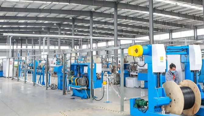
7. Manufacturing of optical fiber cables
The manufacturing process of optical fiber cables is generally divided into the following processes:
1. Screening of optical fibers: Select optical fibers with excellent transmission characteristics and qualified tension.
2. Dyeing of optical fibers: Standard full chromatography should be used for identification, requiring high temperature non fading and non migration.
3. Secondary extrusion: Plastic with high elastic modulus and low linear expansion coefficient is selected to be extruded into pipes of a certain size, and the optical fibers are included and filled with moisture-proof and waterproof materials
The gel of water shall be stored for several days (not less than two days).
4. Fiber optic cable stranding: Twist several extruded optical fibers together with the reinforcing unit.
5. Squeeze the outer sheath of the optical cable: Apply a layer of sheath to the twisted optical cable.
2、 fiber optical cable types
1. According to different transmission performance, distance, and purpose, optical cables can be divided into indoor optical fiber cables, local telecommunication optical fiber cables, long-distance optical fiber cables, and submarine optical fiber cables.
2. According to the types of optical fibers used in optical fiber cables, they can be divided into single mode and multimode optical fiber cables.
3. According to the number of fiber cores inside the optical cable, it can be divided into single core optical fiber cables, multi cores optical fiber cables.
4. According to the different configuration methods of reinforcement components, optical cables can be divided into central reinforcement optical fiber cables, dispersed reinforcement component optical cables, protective layer reinforcement component optical cables, and comprehensive outer protective layer optical cables.
5. According to the different transmission conductor and medium conditions, optical fiber cables can be divided into non-metallic optical cables, ordinary optical cables, and comprehensive optical cables (mainly used for railway dedicated network communication lines).
6. According to different laying methods, optical cables can be divided into duct optical cables, direct burial optical cables, arerial optical cables, and underwater optical fiber cables.
7. According to different structural methods, optical fiber cables can be divided into flat structure optical cables, layer twisted optical cables, skeleton optical cables, armored optical cables, and high-density cores optical fiber cables.
Installation & Connection methods for Fiber Optical Cable`
Over the years, we have developed a mature method and experience in fiber optic cable construction.
Optical cable tool usage:
1 ).pair of fiber optic peeling pliers to peel off the fiber coating/tight cladding
2). combination socket wrenches, 1 set for installation of optical cable splice box/terminal box
3).Measure the length of the peeled optical cable with one 32m tape measure
4). art knives and 1 auxiliary tool for peeling optical cables
5). snakehead pliers, 1 pair to cut the fiber optic cable reinforcement core
6). horizontal cable cutters, 1 vertical horizontal cable stripping tool
7). tweezers, 1 disc optical fiber
8). scissors 1 for cutting fiber optic fibers
9).pliers, 1 for cutting the steel wire in the optical cable
10). pointed nose pliers, 1 auxiliary tool for connection
11). micro screwdriver for 2 fastening screws
12). Allen wrenches 1 set for installing Allen screws
13). adjustable wrenches, 1 auxiliary tool for connection
14). combination screwdrivers, 2 loading and unloading optical cable splice boxes
15 ).alcohol pump bottles, 1 clean fiber optic
16). marker pens, 1 for marking the fiber number
17). flashlights, 1 for night construction lighting
18 ).diagonal pliers, 1 auxiliary construction tool
(1) Outdoor construction of optical fiber cables
The most important thing for laying long-distance optical fiber cables is to choose a suitable path. The shortest path here may not necessarily be the best, but attention should also be paid to land use rights, the possibility of installation or burial, etc.
When turning an optical fiber cable, its turning radius should be greater than 20 times the diameter of the cable itself.
1. construction for aerial fiber optical cables :
A. The overhead method of hanging the suspension wire is simple and inexpensive, and is widely used in China. However, the addition and arrangement of the hook is time-consuming.
B. The hanging wire winding overhead method is more stable and requires less maintenance work. But a specialized binding machine is required.
C. The self bearing overhead method has high requirements for poles, high difficulty in construction and maintenance, and high cost, which is rarely adopted in China.
D. When overhead, a guiding device must be installed at the upper pole of the optical cable to avoid dragging the cable to the ground. Pay attention to reducing friction when pulling optical cables. A section of optical cable for expansion and contraction should be left on each pole.
E. Pay attention to the reliable grounding of metal objects in the optical cable. Especially in mountainous areas, high-voltage power grid areas, and areas with frequent thunderstorms, it is generally necessary to have 3 grounding points per kilometer, and even use non-metallic optical cables.
2. Construction for duct fiber optical cables
A. Before construction, the occupation of the pipeline should be checked, plastic sub pipes should be cleaned and placed, and traction lines should be placed at the same time.
B. Calculate the layout length and ensure that there is sufficient reserved length.
C. The laying length should not be too long at a time (usually 2KM), and the wiring should be pulled from the middle to both sides.
D. The traction force of the cable laying is generally not greater than 120kg, and the reinforcing core of the optical cable should be pulled, and the waterproof reinforcement treatment of the optical cable head should be done well.
E. Cable entry and exit points must be equipped with a guiding device and cannot be directly dragged to the ground.
D. Duct optical fiber cables should also be reliably grounded.
3. Laying of direct burial optical fiber cables
A. The depth of the buried optical fiber cable trench should be excavated according to the standard,
B. Places where trenching is not possible can be laid with overhead or pre buried pipelines drilled.
C. The bottom of the ditch should be smooth and sturdy, and if necessary, a portion of sand, cement, or support can be pre filled.
D. During laying, manual or mechanical traction can be used, but attention should be paid to guidance and lubrication.
E. After the laying is completed, it should be covered with soil and compacted as soon as possible.
4. installation of indoor fiber optical cables
A. When laying vertically, special attention should be paid to the load-bearing issue of the optical cable. Generally, the optical cable should be fixed once every two layers.
B. When optical fiber cables pass through walls or floors, protective plastic pipes with protective openings should be added, and flame-retardant fillers should be used to fill the pipes.
C. A certain amount of plastic pipes can also be pre laid inside buildings, and when optical cables are to be laid in the future, they can be laid using traction or vacuum methods.
4、 Precautions
1. After receiving the optical cable, the user shall check the cable certificate and accompanying optical data, verify the cable reel number, model, number of cores, and length, and inspect the outer packaging for any damage or loss.
2. When laying optical fiber cables, a section of traction rope must be connected to the cable reinforcement, and fixed with a mesh sleeve or tape to the sheath. If it is a pipeline optical cable, a dedicated rotating traction head must be added between the traction rope and the optical cable reinforcement, and it is not allowed to directly pull the outer sheath of the optical cable for traction.
3. For the deployment of optical fiber cables with a length of more than 2KM, it is not allowed to lay them all at once from beginning to end. It is necessary to reel the optical cables in the middle of the section and place them in an inverted 8-shape towards both ends.
4. When unloading optical cables from a car, it is best to use a forklift or crane hoist to gently place the cables on the ground from the car
5. In outdoor construction situations, when unloading optical cables from a car, it is advisable to use a flat and straight board to place it between the car platform and the ground, forming a slope of 45 degrees. A rope is used to pass through the middle hole of the optical cable, and a person is pulling on both ends of the rope on the car, causing the optical cable to slide rapidly along the wooden slope. When unloading optical cables, they should be carefully stacked and placed flat. It is strictly prohibited to directly drop the optical cables from a high place, as they may cause damage due to strong impact.
6. When rolling the optical cable, it should be rolled in the direction indicated by the rotation arrow on the cable reel, but long-distance rolling is not allowed.
7. Before construction, it is necessary to conduct a single disc inspection of the optical cable, such as the quality of the outer sheath and attenuation indicators.
8. The maximum pulling force when laying pipelines or overhead optical cables shall not exceed 1500N, and the maximum pulling force when laying directly buried optical cables shall not exceed 3000N.
9. When constructing and positioning optical cables, bending or forming a 90 degree right angle bend is not allowed; Dynamic bending (such as during construction), for pipelines and overhead optical cables, the bending radius should be greater than 20 times the outer diameter of the optical cable; For directly buried optical cables, the bending radius should be greater than 25 times the outer diameter of the cable; When laying and positioning, the bending radius of pipelines and overhead optical cables should be greater than 10 times the radius of the optical cable; For directly buried optical cables, the bending radius should be greater than 12.5 times the outer diameter of the cable. Avoid severe bending of the optical cable, which can cause a “dead buckle”.
10. During the construction of optical cables, the tensile force shall not exceed the allowable temporary force it can withstand (pipeline and overhead optical cables: 1500N; direct buried optical cables: 3000N; ADSS optical cables: 20% RTS), and during operation and use, it shall not exceed the allowable long-term force (pipeline and overhead optical cables: 600N; direct buried optical cables: 1000N; ADSS optical cables: MAT). The construction of optical cables should be carried out under the guidance of qualified technical personnel.
It is very important to route optical cables in the correct way. Improper construction can lead to increased attenuation, shortened service life, fiber breakage, skin breakage, and armor breakage. Fiber optic cables, especially feed cables, have a larger diameter and heavier weight. When laying out cables, it is necessary to use a bracket to hold the cable reel up, roll the cable reel while pulling the cable. If there is no loose cable without a cable reel, it must be straightened out before wiring. Cable laying personnel and defense personnel should be equipped with walkie talkies to maintain contact. When it cannot be pulled, do not use brute force to pull it. It is important to slowly straighten it out before continuing, Only in this way can we ensure that our “fragile” optical cables are safely laid out.
The main methods include permanent connections, emergency connections, and active connections.
1. Permanent fiber optic connection (also known as hot melt)
This connection involves melting and connecting the connection points of two optical fibers together using a discharge method. Generally used for long-distance connections, permanent or semi permanent fixed connections. Its main feature is that the connection attenuation is the lowest among all connection methods, with typical values ranging from 0.01 to 0.03dB/point. But when connecting, special equipment (welding machine) and professional personnel are required for operation, and the connection point also needs to be protected by a special container.
2. Emergency connection (also known as cold melting)
Emergency connection mainly involves using mechanical and chemical methods to fix and bond two optical fibers together. The main feature of this method is that the connection is fast and reliable, with a typical attenuation of 0.1-0.3dB/point. However, long-term use of the connection point will be unstable, and the attenuation will also significantly increase, so it can only be urgently needed in a short period of time.
3. Activity Connection
Active connection is a method of connecting stations to stations or stations to optical cables using various fiber optic connection devices (plugs and sockets). This method is flexible, simple, convenient, and reliable, and is commonly used in computer network wiring within buildings. Its typical attenuation is 1dB/joint.
The selection of optical cables should not only be based on the number of fiber cores and fiber types, but also on the external sheath of the cable according to its usage environment.
When directly burying outdoor optical cables, armored optical cables should be selected. When overhead, a black plastic outer sheath with two or more reinforcing ribs can be used for optical cables.
2. When selecting optical cables used in buildings, attention should be paid to their flame retardancy, toxicity, and smoke characteristics. Generally, flame retardant can be selected in pipelines or forced ventilation areas
But for Plenum, flame retardant, non-toxic, and smokeless types should be selected in exposed environments.
3. When vertically laying cables inside the building, layer twisted optical cables can be used; When wiring horizontally, breakout cables can be selected.
4. If the transmission distance is within 2km, multimode optical cables can be selected. If the distance exceeds 2km, relay or single mode optical cables can be used.
Standard for buried depth of directly buried optical cables
Remarks on laying section or soil burial depth (m)
Ordinary soil (hard soil) ≥ 1.2
Semi stone (gravel soil, weathered stone) ≥ 1.0
Add 10cm of fine soil or sand from the bottom of the ditch with a total stone mass of ≥ 0.8
Drifting sand ≥ 0.8
Suburbs, villages and towns ≥ 1.2
Urban sidewalks ≥ 1.0
Crossing railways and highways ≥ 1.2 away from the bottom of the ballast or from the road surface
Gully, channel, pond ≥ 1.2
Agricultural drainage ditch ≥ 0.8
How to select a right type of Fiber Optical Cable with high quality
The main purpose of fiber optic selection is to ensure the quality of network connections, reduce fault factors, and identify the fault points of the fiber optic cable. There are many detection methods, mainly divided into manual simple measurement and precision instrument measurement.
1. Manual and simple measurement
This method is generally used to quickly detect the continuity of optical fibers and to distinguish the fibers made during construction. It is achieved by using a simple light source to inject visible light from one end of the fiber and observing which one emits light from the other end. Although this method is simple, it cannot quantitatively measure the attenuation and breakpoints of optical fibers.
2. Precision instrument measurement
Quantitative measurement of optical fibers using an optical power meter or optical time-domain reflectometer (OTDR) can measure the attenuation of the fiber and the attenuation of the joint, and even the position of the fiber’s breakpoint. This measurement can be used to quantitatively analyze the causes of fiber optic network failures and evaluate fiber optic network products
1、 Outer sheath: Indoor optical cables are generally made of polyvinyl chloride or flame-retardant polyvinyl chloride, and their appearance should be smooth, bright, flexible, and easy to peel off. Poor quality optical cables have poor surface finish and are prone to adhesion with the tight sleeves and aramid fibers inside.
The PE sheath of outdoor optical cables should be made of high-quality black polyethylene, with a smooth, bright, uniform thickness, and no small bubbles after cable formation. The outer skin of low-quality optical cables is usually produced with recycled materials, which can save a lot of costs. The outer skin of such optical cables is not smooth, and there are many tiny pits in the outer skin due to impurities in the raw materials. Over time, the outer skin of the optical cables cracks and water enters.
2、 Fiber optic cable: Regular fiber optic cable production enterprises generally use A-grade fiber cores from large factories, while some low-priced and low-quality fiber optic cables usually use C-grade and D-grade fiber optic cables and smuggled fiber optic cables with unknown sources. These fiber optic cables often become damp and discolored due to their complex sources and long delivery times, and multimode fiber optic cables are often mixed with single-mode fiber optic cables. However, small factories generally lack necessary testing equipment and cannot make judgments on the quality of the fiber optic cables. Due to the inability to distinguish such optical fibers with the naked eye, common problems encountered during construction are: narrow bandwidth and short transmission distance; Uneven thickness, unable to connect with the tail fiber; Fiber optics lack flexibility and break easily when coiled.
3、 Reinforced steel wire: The steel wire for outdoor optical cables produced by legitimate manufacturers is phosphatized and has a gray surface. This type of steel wire does not increase hydrogen damage, rust, and has high strength after being formed into cables. Poor quality optical cables are generally replaced with fine iron or aluminum wires, and the identification method is easy – the appearance is white, and can be easily bent when held in hand. The optical cable produced with such steel wire has significant hydrogen loss, and over time, the two ends of the hanging optical fiber box will rust and break.
4、 Steel armor: Regular production enterprises use longitudinal wrapped steel strips with double-sided anti rust coating, while low-quality optical cables use ordinary iron sheet, usually with only one side treated with anti rust treatment.
5、 Loose tube: PBT material shall be used for loose tube of optical fiber installed in optical cable, which has high strength, no deformation and aging resistance. Poor quality optical cables usually use PVC as a casing, which has a thin outer diameter and can be flattened with just a pinch, similar to the straw we use to drink drinks.
6、 Oil paste: Oil paste mainly includes fiber paste and cable paste. Under normal circumstances, fiber paste should fill the entire loose sleeve, while cable paste should fill every gap of the optical cable core under pressure. There are ways to fill the fiber paste with half or less, while some cable paste only applies a layer outside the cable core, while others do not fill the middle between the two ends of the optical cable. This will result in poor protection of the optical fiber, affecting transmission performance such as fiber attenuation, and poor waterproof performance that does not meet national standards. Once the optical cable accidentally leaks water, it will lead to the entire link leaking water and being scrapped. Under normal circumstances, even if there is an accidental seepage, only one section of the seepage needs to be repaired, and there is no need to start over. (The national standard requires a water resistance performance of three meters of optical cable, one meter of water column pressure, and no water leakage for 24 hours.) If poor ointment is used, the above problems can also occur, and it may cause slight bending loss of the optical fiber due to the poor thixotropy of the ointment, resulting in unqualified transmission characteristics of the entire link; If the ointment is acidic, it will also react with the metal materials in the optical cable to precipitate hydrogen molecules, and the attenuation of the optical fiber will rapidly increase when encountering H, causing the entire link to interrupt transmission.
7、 Aramid yarn , also known as Kevlar, is a high-strength chemical fiber that is most commonly used in the military industry. Military helmets and bulletproof vests are made of this material. By 2013, only DuPont and Aksu in the Netherlands were able to produce at a price of around 30 million tons. Indoor optical cables and All Di-electric Self-Supporting optical fiber cables (ADSS) are both reinforced with aramid yarn. Due to the high cost of aramid, low-quality indoor optical cables usually have a very thin outer diameter, which can save costs by using fewer strands of aramid yarn. This type of optical cable is easy to break when threading through the pipe. ADSS fiber optic cables generally do not dare to cut corners because they determine the amount of aramid fiber used in the cables based on span and wind speed per second.
8、 Water blocking tape: Water blocking tape or yarn used for optical cables has strong water absorption performance through uniformly distributed high water absorbing resin inside the product. Under the combined action of immersion pressure, affinity, and rubber elasticity, high water absorbing resin can quickly absorb water several times its own weight. In addition, once the water blocking powder meets water, it will immediately expand the gel. At this time, no matter how much pressure is applied to it, the water will not be squeezed out. Therefore, by wrapping the cable core with a water blocking tape containing water absorbing resin, in case the outer wall of the optical cable is damaged, the high water absorbing resin in the wound area will exert a sealing effect due to expansion, which can prevent the entry of water to the minimum extent. Poor quality optical cables usually use non-woven fabric or paper tape, and once the outer skin of the cable is damaged, the consequences will be very serious.
Common faults of a Fiber Optical Cable and its solutions
The steps for using OTDR testing at endpoints or relay stations to determine obstacle points in optical cable lines are roughly as follows:
1) Use OTDR to test the maximum distance from the obstacle point to the testing end.
2) When encountering natural disasters or external forces such as construction that cause optical cable blockage, the search personnel should follow the obstacle location provided by the maintenance personnel. If it is not for the above situation, it will be difficult for the patrol personnel to find the obstacle location from the abnormal road surface. At this point, it is necessary to verify the distance from the obstacle point measured by OTDR to the testing end with the original test data, and determine which marker stone (or two joints) the obstacle point is approximately located between. After necessary conversion, the specific location of the obstacle can be determined by accurately measuring the ground length between them.
3) If the fiber breakage is caused by a structural defect or aging of the optical cable, and it is difficult to accurately measure its breakpoint using OTDR, only the obstacle section can be detected, then a section of the optical cable should be replaced.
Methods for Improving the Accuracy of Fault Location in Optical Fiber Cable
Firstly, it is necessary to understand how to use the instrument and master the usage method of the instrument, which helps to accurately measure.
1. Set the parameters for OTDR. When using OTDR testing, it is necessary to first set the instrument parameters, the most important of which is to set the refractive index and testing wavelength of the testing fiber. Only by accurately setting the basic parameters of the testing instrument can conditions be created for accurate testing.
2. Use the magnifying function of the instrument panel. By using the amplification function of OTDR, the optical standard can be set at the corresponding inflection point. By using the amplification function key, the graph can be enlarged to 25 meters per grid, resulting in more accurate test results with a resolution of less than 1 meter.
3. Adjust the accurate testing range. For different testing range ranges, the distance resolution of OTDR testing varies. When measuring optical fiber obstacle points, the closest testing range range range range that is greater than the measured distance should be selected in order to fully utilize the accuracy of the instrument itself for measurement.
Secondly, accurate and completed original documents should be established during the maintenance and management process. These accurately completed optical cable line files are the basic basis for fault measurement and positioning. Therefore, in the process of maintenance and management, one should not neglect carelessness and establish true, reliable, and complete line information.
During the monitoring of fiber optic cable connection, the cumulative length of the fiber from the testing end to each joint point and the total attenuation value of the relay section fiber are recorded. At the same time, the testing instrument model and the set value of the refractive index during testing are also registered. Accurately record the remaining of various optical cables. Record in detail the length of the fiber optic cable tray at each joint pit, special section, S-shaped laying, entrance, and other locations, as well as the length of the fiber optic cable tray at the joint box, terminal box, ODF rack, etc., for deduction when converting the length of the fault point route.
In addition, consistency of testing conditions should be maintained during the measurement process. During obstacle testing, it is important to ensure the consistency of the test instrument model, operating method, and instrument parameter settings, in order to ensure comparability of the test results. Therefore, detailed records should be kept of the model of each testing instrument and the setting of testing parameters for future use.
Finally, comprehensive analysis. The testing of obstacle points requires operators to have clear thinking and flexible problem-solving methods, and logical thinking is very useful no matter where. In general, both ends of the fiber optic cable line undergo bidirectional fault testing, and then analyze the original data to prepare to determine the specific location of the fault. When there are no obvious features of the link around the fault point and the specific site cannot be determined, we can adopt the measurement method at the nearby joint, which can be excavated at the obstacle point of preliminary testing, and the end station testing instrument is in real-time measurement state.
Repair of obstacles
If there is an obstacle in the optical cable line, every second must be taken. The circuit should be temporarily adjusted or emergency optical cables should be laid to temporarily seize the circuit, and efforts should be organized to repair it as soon as possible.
1. Emergency repair
1) All fiber optic cable lines in one direction are blocked
According to the predetermined circuit scheduling plan, immediately temporarily connect all or part of the main circuits.
2) Individual fiber optic cable lines in a certain direction are blocked
If there are spare optical fibers or circuitous circuits in the optical fibers, immediately use the spare optical fibers or circuitous circuits to temporarily connect the obstacle circuit; If there are spare optical fibers in the optical cable and no circuitous circuits, they should be handled according to the specified scheduling principles to ensure smooth operation of important circuits and suspend secondary circuits.
3) Partial fiber optic blockage in a certain direction of the fiber optic cable line
If there are spare optical fibers in the optical cable, in addition to using spare optical fibers to temporarily connect the circuit, non blocking optical fibers can be selected for temporary pairing. According to the specified scheduling principles and sequence, the circuit can be temporarily connected. If the temporary paired optical fibers are still not enough and there is no bypass circuit, the secondary circuit will be suspended.
Precautions:
1. The temporary scheduling of the above optical fibers must be jointly discussed and reported to the superior supervisory department for approval by both parties, and completed with close cooperation.
2. The optical fibers paired according to the original line sequence can only be scheduled by the maintenance stations at both ends according to the system and the circuits can be switched; For temporary pairing of optical fibers, they should be adjusted and connected on the connectors of the optical distribution rack (or terminal box) in the relay station on both sides of the obstacle point.
3. If the main optical fiber is connected with an optical attenuator, but the backup optical fiber is not pre connected with an attenuator, the corresponding optical attenuator should also be connected when calling the backup optical fiber. When using temporary pairing of optical fibers, attention should also be paid to this issue.
2. Laying emergency optical cables
1) Conditions for laying emergency optical cables
When all fiber optic cable lines in a certain direction are blocked, after all circuits or major adjustments are made, it is possible to consider repairing the fiber optic cable at once, without the need for an emergency circuit. In the absence of conditions for temporary circuit adjustment, or when some circuits cannot meet the needs of high-capacity communication, emergency optical cables should be laid out, and the circuit should be connected according to the scheduling principles and sequence specified in the “Circuit Dispatching System” to temporarily restore communication, and then a new route should be selected to lay new optical cables for formal repair.
2) Determination of emergency optical cable layout range
When an optical cable is obstructed by natural disasters or external forces, the layout range of emergency optical cables can be determined by determining the approximate location of the obstacle points and easily identifying the obstacle points based on road anomalies. However, when using OTDR to only detect obstacle points at endpoint or relay stations, and cannot determine the specific location of the obstacle, it is difficult to determine the deployment range of emergency optical cables. If conditions permit, OTDR can be used for testing at the opposite relay station. By comprehensively analyzing the test results on both sides, it is generally possible to accurately determine the fiber optic cable break point. If there are no conditions to use OTDR testing from both directions, two different scenarios can be issued for processing:
a) The obstacle point is relatively close to a certain joint, and the emergency optical cable is planned to be laid from this joint. Open this joint and use OTDR to test in the direction of the obstacle at the joint. At this time, the testing distance is short, and the specific position of the obstacle can be accurately measured to determine where the emergency optical cable is laid.
b) The obstacle point is located in the middle of two joints, and it is not suitable to start laying emergency optical cables from a certain joint. Therefore, it is necessary to further determine the position of the obstacle point and lay a section of emergency optical cables on both sides of the obstacle point. When encountering this situation, the gradual extension probing method can be used to locate the specific location of the obstacle, which is to use OTDR to preliminarily measure the obstacle point at the end station or relay station, excavate the optical cable in front of the obstacle point, cut off a certain optical fiber for retesting. If it is found that the obstacle point is not within the cutting range, etc., the approximate distance should be determined, and then excavate the optical cable forward, cut off another optical fiber, and retest again until the obstacle point is included in the cutting point, The deployment range of emergency optical cables can be determined. Generally, the specific location of the obstacle point can be determined by retesting twice.
c) Emergency repair of accelerated connectors for optical cables of the same model
Another method for emergency repair of optical cables is to use the same model of optical cable as the obstacle optical cable as the emergency repair optical cable, and use connectors (flexible joints) and matching liquid for temporary connection to break through the circuit.
3. Formal repair
When formally repairing obstacles in optical cable lines, communication must be maintained as much as possible, especially when important circuits cannot be interrupted. The construction quality must comply with the requirements of the building quality standards and maintenance quality standards for optical cable lines.
When formally repairing the total resistance obstacle of the optical cable line, the following issues should be noted:
1. The obstacles near the joint box or joint should be repaired using the reserved optical fiber inside the joint box or the reserved optical fiber in the joint pit, without the need for additional joints. When there is a reserved optical cable near the obstacle point, it should be used for connection, with only one additional joint added.
2. When it is necessary to formally repair cable obstacles through intervention or replacement of optical cables, the same manufacturer and model of optical cables should be used.
3. The length of intervention or replacement optical cables can be considered by the following three factors:
(1) Considering that the official repair of fiber optic cable splicing requires OTDR monitoring by the end station or relay station, or facilitating the identification of obstacles between adjacent splicing points in daily maintenance work; The minimum length of the intervention or replacement optical cable must meet the response resolution (two point resolution) requirements of the OTDR instrument, and should generally be greater than 100 meters.
(2) Considering that the single-mode optical fiber will not affect its operation under single mode steady state conditions to ensure communication quality, the minimum length of intervening or replacing optical fiber cable shall be greater than 22 meters.
(3) The length of the intervention or replacement optical cable can be flexibly controlled by referring to the principles of (1) and (2) and considering the actual situation comprehensively. For example, if there is an existing joint near the intervention or replacement of the optical cable, the optical cable should be extended to the joint as much as possible, with only one additional joint added.
4. The general order of fiber optic cable cutting during intervention or replacement:
(1) Firstly, according to the scheduling principles and sequence specified in the “Circuit Dispatching System”, both parties of the machine and line should jointly agree on the fiber optic cutting plan and submit it to the superior competent department for approval.
(2) The process of fiber optic cutting should try to avoid interrupting circuits (especially important circuits). When cutting the original newly laid optical fiber from the emergency optical cable, the backup optical cable should be connected first, and the backup optical fiber should be used as a replacement pair. The circuit should be restored pair by pair according to the original cutting order. The intact optical fibers in the original obstacle optical cable should be temporarily paired to adjust the circuit, or if there is no backup optical cable in the original optical cable, the secondary circuit should be suspended. First, the optical fiber of the system should be cut as a replacement pair, and then the original cutting order should be followed, and the pairs should be cut one by one, Restore circuit.
Conclusion:
Over 20 years manufacturing and installation experience, PowerTel and his dedicated engineers having capabilities to provide you a custom design & fabrication of a proper type of fiber optical cable to build up or upgrade your fiber optic communication network; some value engineering & design of your network and offering some valule guides on how to install these fiber optical cable properly and cost effectively and fiber splicing etc. please feel free to contact us if you still have any questions about fiber optical cable and its installation.