As a professional manufacturer of distribution transformer in China, today, we are trying to list all basic knowledge about this distribution transformer, including pad mounted transformer as well.
Distribution transformer, normally refers to a transformer used in an elecitrical distribution system, connecting to local power grid network in his primary side, voltage level is over 1000V, up to 35 kV and linking to switchboard & panel board and distributing power to feed various loads. it is normally pole or pad mounted. It mainly consists of the main body, oil storage tank, insulation sleeve, tap changer, protective device, etc
1. compositions of a distribution transformer
The main body includes three parts: iron core, winding, and insulation oil. The windings and the iron core constitute the core of a distribution transformer, which is the electromagnetic part. The iron core is usually made by stacking hot-rolled or cold-rolled silicon steel sheets with high silicon content, thickness of 0.35 or 0.5mm, and surface coated with insulation paint. There are two basic forms of iron core structure: core type and shell type. The winding is installed on the transformer core column, the low-voltage winding is on the inner layer, and the high-voltage winding is installed on the outer layer of the low-voltage winding. The sleeves made of insulation materials are used to separate the low-voltage winding and the iron core, as well as the high-voltage winding and the low-voltage winding, for easy insulation. The composition of transformer oil is very complex, mainly composed of cycloalkanes, alkanes, and aromatic hydrocarbons. In a distribution transformers, transformer oil has two functions: first, it is used as an insulation material between windings, iron cores, and oil tank. The second is that the transformer oil generates convection after being heated, which plays a heat dissipation role in the transformer core and winding. There are three commonly used specifications of transformer oil: No. 10, No. 25, and No. 45. The grade indicates the temperature at which the oil begins to solidify at minus 25 ℃. The oil specifications should be selected based on the local climate conditions. The oil storage tank is installed on the top cover of the oil tank. The volume of the oil storage tank is about 10% of the volume of the oil tank. There is a pipe connecting the oil storage tank and the oil tank. When the volume of the transformer expands or shrinks with the temperature change of the oil, the oil storage tank plays a role in storing and replenishing oil, ensuring that the iron core and winding are immersed in the oil; At the same time, due to the installation of an oil storage tank, the contact surface between oil and air has been reduced, reducing the rate of oil degradation.
There is an oil mark on the side of the oil storage tank, and next to the glass tube, there are oil level height standard lines for oil temperatures of -30 ℃,+20 ℃, and+40 ℃, indicating the oil level height that transformers that have not been put into operation should reach; The standard line can mainly reflect whether the oil level of the transformer is sufficient when operating at different temperatures.
The oil storage tank is assembled with some open holes in the upper side of a transformer. When transformer oil undergoes thermal expansion and contraction, the air in the upper part of the oil storage tank can enter and exit through the breathing hole, and the oil level can rise or fall to prevent deformation or even damage to the oil tank.
The transformer uses high and low voltage insulation sleeves to lead the leads of the transformer’s high and low voltage windings from inside the oil tank to outside the oil tank, making the transformer winding insulated from the ground (shell and iron core), and it is also the main component that connects the fixed leads to the external circuit. The high-voltage porcelain bushing is relatively tall, while the low-voltage porcelain bushing is relatively short.
Tap changer
it is used to change into different voltage, in accordance with local power gird network.
Protective devices, mainly including gas relays and riot tubes
The gas relay is installed in the middle of the connecting pipe between the transformer oil tank and the oil storage tank, and is connected to the control circuit to form a gas protection device. The upper contact of the gas relay forms a separate circuit with the light gas signal, while the lower contact of the gas relay is connected to the external circuit to form a heavy gas protection. The heavy gas action trips the high-voltage circuit breaker and sends a heavy gas action signal;
Explosion proof tube is a safety protection device for transformers, installed on the large cover of the transformer. The explosion proof tube is connected to the atmosphere, and in the event of a fault, the heat will cause the transformer oil to vaporize, triggering the gas relay to send an alarm signal or cutting off the power supply to prevent the oil tank from bursting.
2. Classification of a distribution transformer
2.1 Classification by installation location
Simply into indoor and outdoor application.
2.1.1 Pole mounted distribution transformer
When the capacity of the distribution transformer is 30KVA or below (including 30KVA), a single pole distribution transformer stand is generally used. Install the distribution transformer, high-voltage drop type fuse, and high-voltage lightning arrester on a cement pole, with the pole body tilted 13 ° -15 ° in the opposite direction of the assembled distribution transformer.
2.1.2 Pad mounted distribution transformer
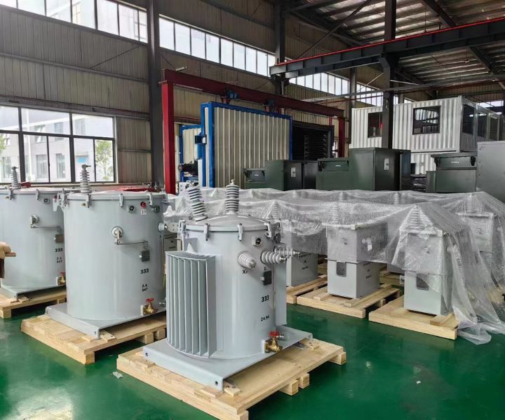
A single-phase transformer refers to a transformer where both the primary and secondary windings are single-phase windings. Single phase transformers have a simple structure, small size, and low losses, mainly due to low iron loss. They are suitable for application and promotion in low-voltage distribution networks with low load density.

The traditional iron core forms are three-phase three core pillars, three-phase five core pillars, involute shaped, etc.
3. Working principle of a distribution transformer
The function of an iron core is to strengthen the magnetic coupling between two coils. In order to reduce eddy currents and hysteresis losses inside the iron, the iron core is made of coated silicon steel sheets stacked together; There is no electrical connection between the two coils, and the coils are wound with insulated copper wire (or aluminum wire). Actual transformers are very complex and inevitably suffer from copper losses (coil resistance heating), iron losses (iron core heating), and magnetic leakage (magnetic induction lines closed by air). To simplify the discussion, only ideal transformers are introduced here. The conditions for the establishment of an ideal transformer are: ignoring the leakage flux, ignoring the resistance of the primary and secondary coils, ignoring the loss of the iron core, and ignoring the no-load current (the current in the original coil when the secondary coil opens). For example, when a power transformer is operating at full load (with the rated output power of the secondary coil), it is close to the ideal transformer situation. Transformers are static electrical appliances made using the principle of electromagnetic induction. When the original coil of a transformer is connected to an AC power source, alternating magnetic flux is generated in the iron core, which is universal φ Represent. In the primary and secondary coils φ It’s the same, φ It is also a harmonic function, as shown in the table φ=φ MSIN ω T. According to Faraday’s law of electromagnetic induction, the induced electromotive force in the primary and secondary coils is e1=- N1d φ/ Dt, e2=- N2d φ/ DT. In the formula, N1 and N2 are the turns of the primary and secondary coils. From the figure, it can be seen that U1=- e1, U2=e2 (the physical quantity of the original coil is represented by subscript 1, and the physical quantity of the secondary coil is represented by subscript 2), with a complex effective value of U1=- E1=jN1 ωΦ、 U2=E2=- jN2 ωΦ, Let k=N1/N2 and measure the transformation ratio of the transformer. From the above equation, it can be obtained that U1/U2=- N1/N2=- k, which is the ratio of the effective values of the primary and secondary coil voltages of the transformer, equal to its turns ratio, and the phase difference between the primary and secondary coil voltages is π. Furthermore, it can be concluded that U1/U2=N1/N2, when the no-load current can be ignored, has I1/I2=- N2/N1, that is, the effective current values of the primary and secondary coils are inversely proportional to their turns, and the phase difference is π. Furthermore, it can be concluded that the power of the primary and secondary coils of an ideal transformer with I1/I2=N2/N1 is equal to P1=P2. The ideal transformer itself has no power loss. The actual transformer always has losses, and its efficiency is η= P2/P1. The efficiency of power transformers is very high, reaching over 90%.
4. Characteristic parameters of a distribution transformer
Rated capacity
The output power of a transformer in its working state, expressed in apparent power. Represented by SN, in units of KVA or VA.
Rated voltage
The voltage value applied between the output terminals of a single-phase or three-phase transformer. Represented by UN, in KV or V. The primary rated voltage is represented by UN1, and the secondary rated voltage is represented by UN2.
Rated current
Refers to the current flowing through the primary and secondary winding terminals of a transformer under rated capacity and allowable temperature rise conditions, expressed in IN and expressed in KA or A. The primary winding current is represented by IN1, and the secondary winding current is represented by IUN21.
Rated frequency
The operating frequency specified during the design of batch transformers. Represented by ƒ N, in Hertz (Hz). The rated frequency in our country is 50Hz.
No load loss
No load loss, also known as iron loss, refers to the active power absorbed by the transformer when a rated frequency baby voltage is applied to the terminals of one winding and the output of the other winding is open circuit. It is expressed in P0 and is measured in W or KW. The no-load loss is mainly composed of hysteresis loss and eddy current loss in the iron core, which are closely related to the material and manufacturing process of the iron core. It is generally believed that the no-load loss of a transformer will not change with the change of load size.
No load current
When the secondary of the transformer is open circuit, there is still a certain amount of current in the primary, which is called no-load current. The no-load current consists of magnetization current (generating magnetic flux) and iron loss current (caused by core loss). For a 50Hz power transformer, the no-load current is basically equal to the magnetization current. Represented by I0. Usually expressed as the percentage of no-load current to rated current, i.e. I0 (%)=(I0/IN) x 100%. The larger the transformer capacity, the smaller the value.
Load loss
Load loss, also known as short-circuit loss or copper loss, refers to the active power consumed by a transformer when a winding with tap connections is connected to its main tap position and connected to the rated frequency voltage, and the output terminal of the other winding is short circuited. The current flowing through the output terminal of the winding is the rated current, expressed as PK. The unit is W or KW. The magnitude of load loss depends on the material of the winding, and the magnitude of load loss during operation varies with the change of load.
Transformation ratio
The ratio of the rated voltage on the high voltage side to the rated voltage on the low voltage side of a batch transformer, i.e. UN1/UN2.
insulation resistance
Indicates the insulation performance between the coils of the transformer and between the coils and the iron core. The insulation resistance is related to the performance, temperature, and humidity of the insulation materials used
Impedance voltage (%)
Phase number
The beginning of three-phase is represented by S, and the beginning of single-phase is represented by D.
connection symbol
In order to distinguish different connection groups, the clock representation method is often used. That is, the phasor of the high-voltage side line voltage is used as the long pin of the clock, fixed on 12, and the phasor of the low-voltage side line voltage is used as the short pin of the clock. When the short pin points to which number, it is used as the label of the connection group. For example, Dyn11 indicates that the primary winding is a (triangular) connection, and the secondary winding is a (star) connection with a center point, with the group number (11).
5. Product model
5.1 Product category code
O-Autotransformer, universal power transformer not marked
H-arc furnace transformer
C-induction furnace transformer
Z-rectifier transformer
K-Mining Transformer
Y-test transformer
5.2 Number of phases
D-single-phase transformer
S-three-phase transformer
5.3 Cooling method
F-air-cooled
W-water-cooled
Note: Oil immersed self cooling and air self cooling are not marked
5.4 Oil circulation method
N – Natural cycle
O-forced guided loop
P-forced loop
5.5 Number of windings
S-Triple winding
Note: Double winding not marked
5.6 Wire Materials
L – Aluminum winding
Note: Copper windings are not marked
5.7 Voltage regulation method
Z – On load voltage regulation
Note: No load voltage regulation marked
5.8 Performance level code (design number)
5.9 Special purpose or special structure code
Z-low noise use;
L — Cable outlet
X – on-site assembly type;
J – The neutral point is fully insulated;
CY – Power plant self use transformer
5.10 Rated capacity of transformer
The rated capacity of the transformer, in KVA.
5.11 Rated voltage of transformer
The rated capacity of the transformer, in KV.
6. Common distribution Transformers
6.1 Oil immersed distribution transformers
It is generally not recommended to use single-phase transformers), can be used indoors (outdoors), can be installed on poles with a capacity of 315kVA and below, ambient temperature not higher than 40 ℃, not lower than -25 ℃, maximum daily average temperature 30 ℃, maximum annual average temperature 20 ℃, relative humidity not exceeding 90% (ambient temperature 25 ℃), and altitude not exceeding 1000m.
6.2 Dry type distribution transformer
7. Box transformer (combined box type substation)
7.1 Overview
Box type substation, also known as prefabricated substation or prefabricated substation.
In recent years, the load density of low-voltage power supply has been continuously increasing, which has put forward high requirements for the reliability and quality of power supply. In this case, if a large capacity substation is used as the center and low-voltage power is supplied to surrounding users, it will consume a large amount of non-ferrous metals, resulting in significant energy loss and cannot guarantee the quality of power supply. On the contrary, if high voltage is applied deep into the load center and a substation is built in the load center, it can shorten the low-voltage power supply radius, improve power supply quality, save non-ferrous metals, and reduce power loss. It is most suitable to build a box type substation in the load center.
High voltage/low voltage prefabricated box type substations (substations), also known as box type substations or combination type substations (combination box type substations), complete substations, and mobile substations, emerged in the 1970s and have been produced by several domestic manufacturers. Its structure is generally a box type structure, consisting of three parts: a high-voltage switch compartment, a transformer compartment, and a low-voltage distribution switch compartment. The rated voltage is 10 and 35kV, and it can install transformers of 1600kVA and below. Its characteristics are: small footprint; Factory production, fast speed, and good quality; Fast construction speed, only requiring on-site construction of the basic part; Beautiful appearance, able to coordinate with the residential environment; Strong adaptability, interchangeability, and easy standardization and serialization; Low maintenance workload, saving investment.
Therefore, box type substations are highly valued and welcomed both domestically and internationally, and can be widely used as very promising electrical equipment. They have been widely used in factories, mines, oil fields, ports, airports, stations, urban public buildings, concentrated residential areas, government offices, schools, commercial halls, and underground facilities.
At present, there are many types of combined substations with different models in China, including outdoor, indoor, fully enclosed, semi enclosed, corridor free, combined, fixed, and installed, dry-type transformers, oil immersed transformers, terminal power supply, ring power supply, etc., which can meet the needs of different users. The arrangement of high voltage, transformer, and low voltage three compartments is in the form of a grid arrangement or a grid separation scheme. The components of the high-voltage chamber equipment are selected from imported, domestically produced or imported ring main cabinets, load switches with current limiting fuses, and vacuum circuit breakers. The low-voltage room is composed of power, lighting, metering, and reactive power compensation cabinets. Ventilation and heat dissipation are equipped with fans, automatic temperature controllers, and anti condensation controllers. The shell of the box is mostly made of ordinary or hot-dip galvanized steel plate, aluminum alloy plate, and the skeleton is welded with formed steel or connected with bolts.
7.2 Classification
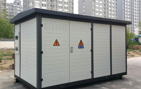
The box variant can be divided into European, American, and integrated styles. European style box transformer is a compact complete power distribution device that combines a transformer as a separate component, including a high-voltage cabinet, transformer, and low-voltage cabinet, and combines them into one or several boxes according to a certain wiring scheme. There are two ways to construct the box, namely the “eye” shaped layout and the “product” shaped layout. The “eye” shaped arrangement of high and low voltage rooms is relatively wide, making it easy to implement a ring network or dual power supply connection for ring network power supply solutions.
The high-voltage chamber of European style box transformers is generally composed of high-voltage load switches, high-voltage fuses, and lightning arresters, which can be used for power outage and short circuit protection. The low-voltage room is composed of a low-voltage air switch, current transformer, ammeter, voltmeter, etc. Transformers are generally S9 or dry type.
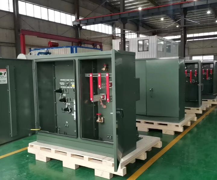
The American style box type combination transformer has a structure divided into two parts: front and rear. The front part is a wiring cabinet, which includes high and low voltage terminals, high-voltage load switches, plug-in fuses, high-voltage tap changer operating handles, oil level gauges, oil temperature gauges, etc; The rear is the fuel tank body and heat dissipation fins, and the transformer winding, iron core, high-voltage load switch, and plug-in fuse are all located inside the fuel tank body. The box adopts a fully sealed structure. The integrated box has recently been developed by domestic manufacturers, but its application is not yet widespread. It is a double-layer structure, with high and low voltage rooms placed above the transformer room.
European, American, and integrated box transformers each have their own advantages and disadvantages. European box transformers have a larger volume, and high and low voltage switches and transformers are all located in a large shell, which has poor heat dissipation conditions and requires the installation of mechanical exhaust devices. American style box transformers have relatively good heat dissipation conditions due to the direct external heat dissipation of transformer cooling fins, but their appearance is worse than European style, making it difficult to match with green environments such as residential communities. The integrated box transformer in a compact design and has similar advantages and disadvantages to American box transformers. In addition, American and integrated box transformers can only be manufactured in China with a capacity of 630kVA or less, while European box transformers can reach 1250kVA.
The models of ordinary box type substations are divided into three categories
(1) High voltage switchgear model;
(2) Dry type transformer cabinet model;
(3) Low voltage switchgear model.
The meaning of the first three letter symbols is:
Z-combination; B – Substation; N (W) – indoor (outdoor, optional); X-box type; Y-Mobile.
7.3 Basic structure
The structure of a box type substation is related to the space required for various wiring equipment. The ring network and terminal power supply line schemes are designed in two categories: enclosed and semi enclosed. The high and low equipment rooms are divided into structures with and without operating corridors, which can meet the needs of any combination of six load switches, vacuum switches, etc. The high voltage room, transformer room, and low voltage room are arranged in a straight line, and there are two types of designs according to transportation requirements: integral and modular disassembly.
The box body adopts two types: steel plate interlayer (which can be filled with asbestos) and composite board, and the top cover is sprayed with colored sand latex. The box has rainproof performance. To monitor, inspect, and replace equipment, a universal door needs to be designed, which can be opened with two or a single leaf. The transformer room is equipped with a structure with doors on both sides. The transformer compartment has tracks for the movement of the transformer (nameplates and danger signs are prominently placed on the outer shell).
The high and low voltage sides of the substation should be equipped with doors of sufficient size. The doors should be pulled outward, with handles, locks, and concealed latches on the doors. The opening angle of the doors should not be less than 90 °, and there should be corresponding interlocks for the opening of the doors. The high-voltage side meets the requirements of “five defenses”. In the case of non electrification, there is a reliable grounding device after the door is opened. Only when there is no voltage signal indication can the electrified part be repaired. After the high and low voltage side doors are opened, there is a lighting device to ensure the safety of operation and maintenance.
The shell has ventilation holes and insulation measures, and if necessary, heat dissipation measures can be taken to prevent excessive internal temperature. The air temperature inside the small room of high and low voltage switchgear should not cause the temperature of each component to exceed the corresponding standard requirements. At the same time, measures are also taken to ensure that there is no condensation inside when the temperature changes sharply. When there is a ventilation opening, there should be a dust filtering device.
The incoming and outgoing methods of a box type substation can be one of the following four: overhead line in and out, cable in and out, overhead line in and out, and cable in and out of the overhead line.
The high-voltage receiving equipment of box type substations adopts a scheme of connecting high-voltage load switches in series with fuses. This scheme has been widely used in the field of urban power distribution abroad, especially as a high-voltage receiving protection scheme for box type substations. This is mainly due to:
(1) This protection scheme can basically meet the load conditions of most box type substations, which can control and cut off normal load current, and also withstand and protect short circuit faults.
(2) Due to its small size, it is easy to implement a high-voltage ring network solution in limited space, thus better highlighting the small volume of box stations.
(3) The circuit is simple and the maintenance workload is small, making it particularly suitable for the actual use of unmanned box type substations
(4) The cost has been greatly reduced. The cost of circuit breakers is usually 2-3 times that of load switches with the same rated parameters. The use of high-voltage load switches connected in series with fuses instead of circuit breakers highlights the unique characteristics of box type stations and increases their competitiveness with civil engineering substations.
At present, almost all domestic production plants are using this high-voltage protection scheme, which is the development direction of high-voltage receiving equipment in box type substations.
The 10kV distribution equipment in box type substations commonly uses load switches, fuses, and ring network power supply devices, which are connected from adjacent overhead lines to the high-voltage end of transformers. The incoming method can be cable or overhead insulated wire. As a public box type substation, the low-voltage output of the box type substation depends on the transformer capacity, generally not exceeding 4 circuits, and not exceeding 6 circuits at most. It can also have one main output line and branch power supply to the adjacent distribution room. When using a box type substation as an independent user, one circuit power supply can be used.
At present, most box type substations are equipped with lightning arresters as overvoltage protection for transformers and other high-voltage receiving equipment in the station.
The low-voltage side main switch of domestic box type substations generally adopts three types of automatic switches: DZL0, DWl0, and DWl5. The electrical appliances used on the low-voltage side branch mainly include BM and BT series fuses and DZ and DW series automatic switches. When the transformer capacity of the box type substation is 200-630kVA, DWl0 or DWl5 is used as the low-voltage main switch. When the capacity exceeds 800kVA, DWl5 switches should be used as much as possible.
7.4 Introduction to Common Box Transformers
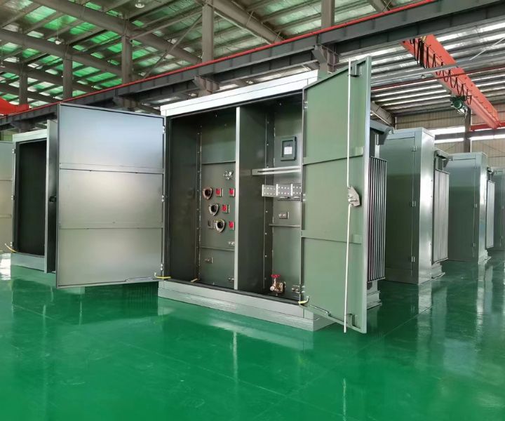
The American style box type transformer is a unified design of equipment such as transformers, load switches, and protective fuses. The windings and cores of transformers, high-voltage load switches, and protective fuses are all in the same oil filled box, without relatively independent high and low voltage switchgear. The box body is a fully sealed structure, using concealed high-strength bolts and silicone to seal the box cover; The low-pressure chamber is separately located outside the fuel tank. The American box type transformer is divided into two parts: front and back. The front is the high and low voltage operation interval, which includes high and low voltage bushings, load switches, no-load voltage tap changers, plug-in fuses, pressure relief valves, thermometers, oil level gauges, oil injection holes, oil drain valves, etc; The rear part consists of a box and heat dissipation fins.
European style box type transformer (pre installed substation) is a device that places high-voltage switchgear, distribution transformers, and low-voltage distribution devices in three different compartments and achieves electrical connections through cables or busbars. The high and low voltage switchgear is relatively independent and compact, and is pre installed with the transformer in a box that can be lifted and transported. The transformer room, high voltage room, and low voltage room are all equipped with independent doors, so their volume is larger than American box type.
Buried transformer is a compact combination distribution facility that installs transformers, high-voltage load switches, and protective fuses in oil tanks, and is placed in a pit during installation. It has the characteristics of not occupying space, being able to operate in water for a certain period of time, and being maintenance free, which is conducive to saving the area occupied by urban power distribution facilities. Therefore, it has a wide range of application prospects in urban network renovation and construction.
8. Underground box transformer
8.1 Overview
With the acceleration of urban and rural modernization construction, urban construction has entered the urban beauty stage aimed at improving the street view and appearance. The traditional box type substations are scattered and disorderly, occupying the golden ground of the bustling city, which is out of place with the beautiful urban environment. The requirements for power equipment in urban planning, highway construction, and public facilities are becoming increasingly high. In developed countries such as Europe, the United States, and Japan, transformers have gradually been buried underground for installation in accordance with urban ecological design concepts.
The buried box transformer is a new type of complete power equipment designed and developed to meet the requirements of the above fields. The buried box transformer mainly consists of buried transformers and outdoor switchgear with advertising light boxes. Buried transformer is a new type of compact substation equipment composed of a transformer, high-voltage load switch, fuse, etc. It is installed in a pit, does not occupy surface space, and can operate submerged in water for a period of time. The advertising lightbox outdoor switchgear is a hybrid structure that integrates billboards and outdoor switchgear, installed on the ground. The interior of the box is an outdoor high and low voltage distribution cabinet, with advertising light boxes on both sides, which have excellent visual effects. The buried box transformer conforms to the urban ecological design concept, occupies a small area, beautifies the environment, and is suitable for urban transportation arteries, residential communities, airports, stations, highways and other places. It will become a trend for the renovation of urban distribution network equipment.
The buried box transformer mainly consists of buried transformers and outdoor box type switchgear. Buried transformer is a new type of compact substation equipment composed of a transformer, high-voltage load switch, fuse, etc. It is installed in a pit, does not occupy surface space, and can operate submerged in water for a period of time. Box type outdoor switchgear is a hybrid structure that integrates outdoor switchgear and is installed on the ground. The interior of the box is an outdoor high and low voltage distribution cabinet, which occupies a small area and does not affect the ground building facilities.
8.2 Characteristics
8.2.1 Underground combination distribution transformer
The underground combination transformer used in the buried box transformer has the following characteristics:
(1) The box is made of stainless steel, fully sealed, with a protection level of IP68, and can be immersed in water for operation.
(2) The high and low voltage incoming and outgoing lines adopt a waterproof, fully sealed, fully insulated, and fully shielded wiring method for safer operation.
(3) Using cyclohexane based transformer oil to ensure good heat dissipation ability,
(4) Amorphous alloy iron core can be used, which has a significant energy-saving effect.
(5) High insulation and heat resistance, environmentally friendly.
(6) Backup and plug-in fuses provide safer protection for transformers.
(7) The load switch has two, three, and four position forms and is suitable for various power supply systems.
8.2.2 Prefabricated pit foundation
The foundation of the underground box transformer is prefabricated in the factory, and the prefabricated foundation has the following characteristics:
(1) The foundation of the pit can be pre pressed with steel plates of 6mm or more, with a fully sealed structure to ensure that surface water and other debris cannot enter the pit. Prefabricated reinforced concrete structures can also be used, with advanced waterproof technology to ensure that the foundation does not leak,
(2) There is a collection pool at the bottom of the pit, and a submersible pump controlled by an automatic drainage system can be installed.
(3) There are high and low voltage cable installation brackets installed in the pit for easy cable installation and fixation.
(4) Waterproof lighting is installed in the pit for easy maintenance.
(5) The foundation top cover is equipped with an openable access hole.
8.2.3 Box type outdoor switchgear
(1) The protective casing of the switchgear adopts a box structure, and the two doors of the casing can be opened at full angles. It is supported and positioned by pneumatic springs for easy operation and maintenance of the switchgear.
(2) The box transformer is equipped with an insulation layer, which has a good insulation effect.
(3) The switchgear adopts a double-layer door structure, and the protection level meets national standards.
(4) The fan hidden inside the box transformer can automatically exhaust and supply air to the foundation of the pit to reduce temperature.
▲ Structural layout
8.3 Waterproofing
8.3.1 Waterproofing treatment for buried transformers
Although the underground combination transformer of the buried box transformer is allowed to operate submerged in water, in order to ensure the long-term safe and reliable operation of the underground transformer, the waterproofing and drainage inside the pit foundation must be comprehensively considered and designed.
For areas with low groundwater levels (lower than the bottom of the pit foundation), a prefabricated pit structure is adopted, and the ventilation holes at the top of the pit have effective ventilation and rainproof capabilities. The bottom of the pit foundation is laid with flowing sand and gravel, and water can directly penetrate into the ground. For areas with high groundwater levels (higher than the bottom of the pit foundation), a prefabricated fully enclosed concrete pit structure is adopted to prevent surface water flow and groundwater infiltration into the pit.
8.3.2 Heat dissipation of buried transformers
The underground box transformer mainly ensures the temperature rise and heat dissipation of the underground transformer from the following aspects:
(1) The underground transformer adopts S11 series low loss products or amorphous alloy iron core products, which greatly reduce no-load loss and load loss, so the heat generation is low.
(2) The transformer has a high heat resistance level, a large temperature rise margin, and also improves the overload capacity of the transformer.
(3) Between the distribution box and the foundation pit, inlet and outlet fans are installed. When the temperature rise of the underground combination transformer reaches the set value, forced supply/exhaust cooling is carried out to ensure the normal operation of the underground transformer.
8.4 Technical advantages
8.4.1 High reliability
The casing of the buried transformer box selected for the underground transformer substation is made of anti-corrosion stainless steel, fully sealed, and the high and low voltage incoming and outgoing lines are connected in a waterproof, fully sealed, fully insulated, and fully shielded manner. It ensures the anti-corrosion and sealing ability of the buried distribution transformer, with an overall protection level of IP68, and can operate under short-term immersion in water.
High voltage plug-in and backup fuses can be quickly cut off in case of failure of the distribution transformer, without affecting the overall circuit.
Waterproofing and drainage considerations were taken into account in the design and production of the transformer pit foundation. The top ventilation hole has effective rainproof and waterproof functions, and the sides and bottom are treated with special waterproof materials, preventing water infiltration. An automatic buried box transformer is installed at the bottom, which can be submerged in water for operation and can withstand flood disasters. All measures ensure a 20-year service life of the buried transformer, which can be maintenance free and inspection free, effectively improving the reliability of the power supply system.
8.4.2 High degree of automation
The buried box transformer can be operated through a comprehensive control device for underground transformers using GPRS wireless network technology, which reports the operation status of underground combination transformers and low-voltage equipment to the control center or equipment management personnel. It can also achieve remote control and electrical operation of high-voltage circuit breakers, greatly facilitating the operation and use of underground combination transformers.
8.4.3 Comparison with ordinary box transformers
Generally, box transformers occupy a large area and are difficult to coordinate well with the environment. Especially in some high-end residential areas where new roads are built, the distribution facilities or box type substations scattered on the community and roads cannot be coordinated with the community and road environment, affecting the overall aesthetics of the community and roads, and even affecting the urban landscape of the roads.
And the buried box transformer, because the transformer is installed underground, does not affect the surrounding environment. The distribution box installed on the ground has a small volume and is easy to coordinate with the surrounding environment. In residential areas, the ground distribution box can be matched with the greenery of the community, becoming a part of the community’s scenery. The distribution box on the ground can also be designed as an advertising light box.