A Best Hydro Turbine Generator Manufacturer in China since 1955
As one of leading manufacturer of hydro turbine generator manufacturer in China, We are
- Over 70 years manufacturing Experience
- In-house testing facilities for routine & type test
- Provide 36 months warranty of quality and performance
- 24/7 online technical support available for technical consulting
Hydro Turbine Generator
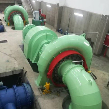
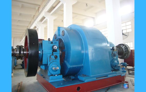
A hydro turbine generator is a device composed of a water turbine and a generator that convert water flow energy into rotating mechanical energy. It is a most important equipment in a hydro power plant and performs the function of converting water energy into electrical power. Over 70 manufacturing experience, PowerTel and his dedicated engineering team can provide you a full range of Hydro turbine generator, excitation equipment, power transformer & electrical switchgear, wire & cable, manual or automatic speed governor, power plant valve, high capacity pump, electrical motor and its package solution for your hydro power plant.
Main types of Hydro Turbine Generator


Hydro Turbine Generator Classcified by its Associated Water Turbine
We are available for Francis, Kaplan, Pelton, Turgo & Tubular turbines, a single unit up to 500 MW; The power capacity of various types of water turbines is determined by water head and flow rate of a power plant. The amount of electricity that can be generated depends on the size of the hydro turbines and its generators. All these water turbines & its generators are developed to adapt to different water head and flow; Each type turbine & its generator has its most suitable head and flow range. So for every power station, we need to design and select a best one to fit your hydro power plant.
-
 Kaplan Hydro Turbine Generator
 -
 Pelton Hydro Turbine Generator

Hydro Turbine Generator Categoried by its Capacity
-
 160 kW Hydro Turbine Generator

Product Feature Box


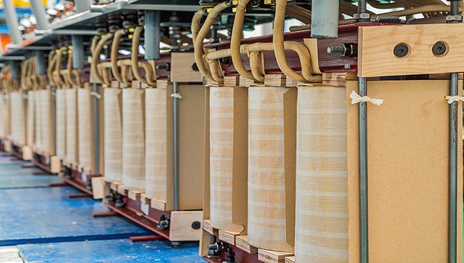
Our Manufacturing Facilities for Hydro Turbine Generator
Over 70 years manufacturing experience of this hydro turbine generator, supplied & installed in thousands of hydro power plant around the world.
Complete Product Chain for Your Hydro Power Plant
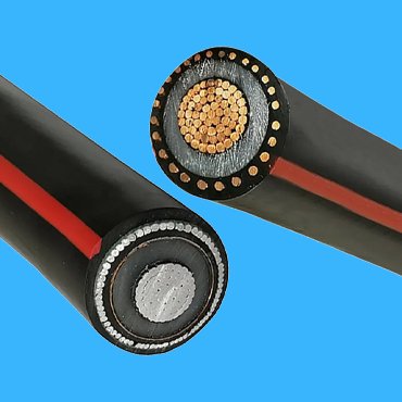
Through our complete product chain and good relationship with some other electrical equipment, we are able to provide you a package supply of all materials for the construction of your dams and its hydro power plant, power transmission & distribution lines and its associated electrical susbtations up to 500 kV. and help you build a new power plant or rehabilitate an old one at lowest possible costs.
24/7 Online Technical Consultancy and On-site Technical Support
Through years of our experiennce for building a hydro power plant, our dedicated engineers can answer you any questions about your new hydro power plant or an existing one. from initial feasible study, value engineering design , preparation of tendering documents and bid evaluation, techncial supervision to final connection to local power Grid Network.

Difference Between Brushed And Brushless Hydro Turbine Generator
The difference between a brushed and a brushless hydro turbine generator is as follows:
Structural difference: The most intuitive difference lies in the presence or absence of carbon brushes. Brushless generators do not have brushes and commutators, while brushless generators contain these components. In addition, the stator and rotor structures of the two are also opposite; In a brushless generator, the coil is a part of the rotor and rotates together with the commutator, while in a brushless generator, the permanent magnet serves as the rotor and the stator is the coil part.
Working principle: Brushless hydro turbine generators rely on mechanical brushes and commutators to change the direction of current and generate a magnetic field to drive the motor to work. Brushless generators use electronic switches instead of mechanical brushes and inverters to complete this process, and the controller provides different directions of direct current to achieve alternating current direction in the motor coil. two
Service life and maintenance: Due to the fact that the brushes of a brushless hydro turbine generator are easily worn parts and require regular replacement and maintenance, their service life is relatively short (usually 2-3 years). In contrast, brushless generators have a longer service life (typically up to 7-10 years) and lower maintenance costs due to the lack of friction loss and maintenance requirements for brushes. thirteen
Energy consumption and efficiency: Brushless hydro turbine generators lose less energy during the energy conversion process and are usually more efficient than brushless generators. At the same time, due to its reduction of friction loss and electrical spark interference, it can more effectively convert electrical energy within a certain range and provide stable output. However, under certain specific conditions such as low load, the efficiency may be slightly inferior to that of a brushless motor. twenty-three
Noise and heat generation: Due to the absence of frictional sound and electrical spark interference caused by physical contact, it performs excellently in terms of smooth operation, noise control, and reducing heat generation. This makes it particularly suitable for use in situations or equipment with high requirements for the working environment.
Price and application areas: Although the initial investment of brushless hydro turbine generators may be higher than that of similar level brushed products (due to the need for additional controllers, etc.), in the long run, considering the saved frequent maintenance costs and time costs, it is still very cost-effective. it is widely used in the shipbuilding industry, electric vehicles, and other fields according to their respective characteristics.

Related Product


More introductions of Hydro Turbine Generator
The hydro electric generator is the core equipment in a hydro power plant. In order to monitor, control, and ensure a smooth working operation of hydro turbine generator units, achieve safety, reliability, and economic efficiency, a complete set of auxiliary equipment systems need to installed in the hydro power plant as well, such as fast water in-take gates, turbine hydraulic oil systems, compressed air systems, water supply pump and drainage systems, and automation & control equipment (automatic excitation devices, speed governor, water turbine automatic control systems, and automation components, etc.). With the continuous development and widespread application of modern computer technology, the comprehensive automation level of hydro power plant is also constantly improving. Many large and medium-sized hydro power stations have adopted computer monitoring to achieve unmanned (few people on duty), and there are many electromechanical and control equipment in hydropower stations.
A hydro turbine generator mainly composed of rotor and stator, there is a main lead out cable on the stator bracket, and the current emitted enters the busbar through the cable. In order to prevent the temperature of the hydroelectric generator from being too high during power generation operation, the generator is equipped with ventilation and cooling equipment.
In order to establish a rotating magnetic field during the power generation process, the unit is equipped with a permanent magnet machine to provide a magnetic source, and the excitation system provides excitation current to the generator. The torque transmission between the main shaft of the water turbine and the main shaft of the generator varies depending on the unit. For small units with larger capacity, direct connection is adopted, which is connected by bolts through the main shaft flange; Units with a single unit capacity below 400kw will use indirect connections, such as gears, friction wheels, and belt drives.
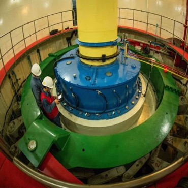
In order to maintain the normal operation of the hydro turbine generator, it is necessary to set up a support or guide bearing between the foundation and the main shaft to withstand the radial and axial forces of the main shaft, and adopt lubrication measures to reduce friction between the main shaft and bearings, reduce wear, and improve energy utilization. The arrangement of bearing systems in hydroelectric generator sets varies, and the position of radial thrust bearings that bear axial forces determines the structural layout of the unit.
The supporting system of the hydroelectric generator set is equipped with corresponding lubrication and cooling systems, and the temperature of the bearing is strictly controlled to ensure the normal operation of the unit.
In order to prevent the low-speed operation of the unit from burning out the bearing shells during shutdown, it is necessary to set up a braking device to apply compressed air for braking.
The governor is the control equipment of a hydroelectric generator set. When the user’s load changes, the speed or frequency change signal is input to the governor, and the governor operates to drive the relay to change the opening of the guide vanes, achieving changes in the flow rate into the turbine and the output of the unit, and achieving a new balance with the user’s load. There are two working modes of speed controllers: automatic and manual, and most small hydropower stations use manual operation.
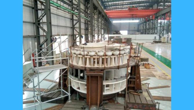
Installation of a hydro turbine generator
A hydroelectric generator is a set of machines consisting of a water turbine and a generator driven by it, used to convert mechanical energy from water bodies into electrical energy. The installation of water turbine generator units in hydropower plants is a key task for the operation of the units. The quality of installation is directly related to the safe and economic operation of the power station in the future.
(1) Install commonly used lifting equipment
The lifting equipment for the installation of hydroelectric generators includes bridge cranes, slings, and lifting tools, as well as temporary hoists and jacks.
Bridge cranes in hydropower stations can be divided into electric bridge cranes, electric double beam or electric single beam cranes, and manual double beam or manual single beam cranes according to their structure and power.
(2) Installation of water turbine generator units
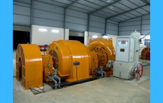
The layout of hydroelectric generators depends on the water turbine, usually small and medium-sized impulse turbines and tubular turbines are equipped with horizontal generators; Large and medium-sized mixed flow turbines and axial flow turbines are equipped with vertical generators. Vertical hydro generators are further divided into suspended hydro generators and umbrella hydro generators. In addition, there is a reversible dual speed power generation electric motor for pumped storage.
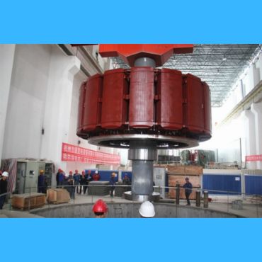
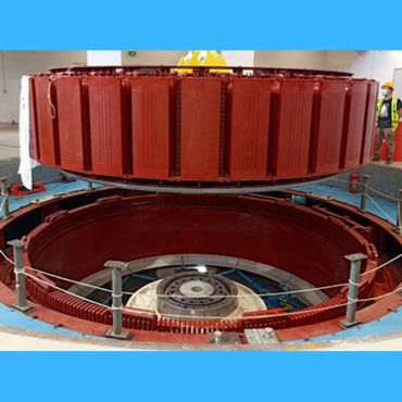
1. Installation of suspended hydro generator
(1) Embed the foundation components of the lower wind tunnel cover plate, lower frame, and stator in the first phase concrete of the foundation pit.
(2) Assemble the stator and lower coil in the stator pit (or assemble the stator in the installation room and lift it into the pit as a whole).
(3) After all the large components of the water turbine are lifted into the pit, lift the lower wind tunnel cover plate.
(4) Lift the assembled lower frame into the foundation and align it, and pour the second phase concrete.
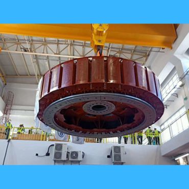
(5) Assemble the rotor on a specially designed assembly platform in the installation room, then lift it into the turbine pit as a whole and adjust the positioning according to the center, elevation, and level of the water turbine spindle.
(6) Measure the air gap between the rotor and stator, correct the center of the stator based on the rotor, make the air gap around uniform, and pour the second phase concrete of the stator foundation.
(7) Hang the assembled upper frame onto the stator frame, adjust the center and level according to the rotor spindle, tighten the frame assembly bolts, and drill shear positioning pins.
(8) Assemble the thrust oil groove and thrust bearing, place the rotor on the already scraped thrust bearing, perform a separate turning of the generator spindle, measure and adjust the spindle swing.
(9) Connect the generator and the main shaft of the water turbine to measure and adjust the overall axis swing of the unit.
(10) Adjust the force on the thrust pad and adjust the center and perpendicularity of the unit axis according to the clearance of the turbine’s leak proof ring. According to the position of the spindle and the direction and size of the journal swing, install the scraped guide bearing shells of each part, assemble the unit air cooler, oil, gas, water pipes, and other accessories.
2. Installation of double bucket wheel large horizontal hydroelectric generator
(1) Embedding of basic components.
(2) After scraping the bearing shell, lift the bearing seat onto the foundation component.
(3) Remove the segmented stator during installation and lift the lower half of the stator onto the foundation plate.
(4) Measure and adjust the concentricity of the bearing seat and stator.
(5) Assemble the rotor in the installation room and lift it as a whole onto the bearing seat.
(6) Based on the main shaft flange of the water turbine, further correct the position of the bearings to make the generator main shaft flange concentric and parallel to the main shaft flange of the water turbine, and perform a turning inspection. After finely scraping the bearing shells, assemble the bearings and oil pipes.
(7) Lift the upper half of the stator into combination with the lower half of the stator, and connect and insulate the stator coils.
(8) Measure and adjust the axis of the unit by turning the gear, and connect the main shaft.
(9) Measure the air gap between the rotor and stator, verify the center position of the stator, and fix the foundation bolts.
(10) Install the stator end cover and other accessories. The stator and rotor of a small horizontal hydroelectric generator are transported to the site as a whole, and the installation is carried out using the method of stator sleeve rotor or rotor sleeve stator for large components. Other installation methods are similar to those of the horizontal generator mentioned above.
Maintenance rules for a hydro turbine generator
Different hydraulic units use different equipment models, so the monitoring and inspection items during unit operation are also different. Below are only the common inspection items listed.
The following situations should strengthen the inspection of the maneuverability of the water turbine: the first operation of the water turbine after maintenance and the operation of new equipment; Put the water turbine into operation after handling the accident; The water turbine has serious equipment defects that have not been eliminated: the water turbine operates with excessive active and reactive power; The leakage of the top cover is large or the drainage of the top cover is not smooth; High water level during flood season or downstream; Running or conducting vibration tests in the vibration zone; After the experimental work is completed. In order to ensure the safety and reliability of the normal operation of the equipment, the main and auxiliary equipment should undergo regular tests, switch maintenance work according to regulations, and promptly notify maintenance personnel to handle any problems found. Under normal circumstances, the crew should regularly perform the following tasks:
(1) Switch the oil pump of the oil pressure device.
(2) Switch the working oil pump of the water inlet working gate.
(3) Inject oil into each connecting rod joint of the governor.
(4) Governor filter switching.
(5) Measure the swing of the main shaft of the generator and water turbine.
(6) According to the requirements of the thrust bearing oil film of the standby unit, the rotor should be regularly pushed or manually started and idle once.
(7) According to the water level and water quality, select the water intake in a timely manner to ensure the water quality requirements.
(8) The filter of the unit cooling system is regularly cleaned and discharged.
(9) Each gas water separator is regularly drained and discharged.
(10) The technical water supply main of the unit is regularly flushed and silted.
(11) The unit cooling system operates regularly in both forward and reverse directions, and the air cooler is clogged.
The monitoring items after the water turbine starts up include: monitoring whether the vibration of the water turbine is normal; Monitor whether the braking device of the unit is in normal working condition and whether it can be started at any time; Check if the indicators on the monitoring machine are normal; Monitor whether the water pressure of each part of the unit is normal; Monitor whether the swing of the unit and the operation of the water guide bearing are normal; Monitor whether the main shaft seal and top cover drainage of the water turbine are normal; Monitor whether the connection parts of the mechanical hydraulic mechanism of the speed controller are in good condition, whether the electrical control circuit is normal, and whether the active power regulation action is normal; Monitor whether the unit signal and operating power supply are normal; Monitor whether equipment operation projects related to mechanical and electrical systems are completed.
The monitoring items after the shutdown of the water turbine include: whether the connections of various components of the governor are abnormal; Whether the oil pressure device and oil system are abnormal; Whether the oil level of the unit bearing is normal; Whether the rotating part of the unit is abnormal; Is the braking system in a reset state; Whether the technical water supply system related to unit shutdown is normal; Is the leakage of the top cover of the water turbine large; Whether the guide vanes are fully closed and whether the shear pin is cut off; Is the indication of each indicator instrument on the machine side control panel normal.
The inspection and maintenance items of the oil pressure device include: whether the pressure in the pressure tank is normal, whether the oil level is normal, and whether there is any oil or gas leakage phenomenon; Whether the pressure measurement and control device is working properly; Whether the oil level and quality of the oil collection tank are qualified, and whether there are any abnormal oil level signals; Whether the positions of each valve are correct and whether the safety valve is working properly; Whether the motor leads and grounding are intact, whether the voltage indication is normal, and whether the pressure oil pump is working properly.
The inspection and maintenance items of the speed controller system include: stable operation of the speed controller, no abnormal pulling, jumping, and swinging phenomena; During normal operation, the speed indicator is at 100%, the balance meter is at the balance position, and all indicator lights on the electric control panel are normal; Opening limit, manual and automatic switching valve, and accident solenoid valve in corresponding positions; When a significant difference is found between the oil pressure of the governor and the pressure tank, the filter should be switched and cleaned; The electro-hydraulic converter operates normally; All connecting components and pipelines are well connected, without any looseness, detachment, or oil leakage; The opening indication during manual operation matches the actual opening; All power switches and fuses in the electrical cabinet are in the on state, the power indicator light is normal, and the fan is running normally; The indicator light on the control device board indicates normal operation, and the selection switch position is correct; There are no abnormal conditions such as overheating, detachment, or wire breakage in all electrical components; When the unit is in stable operation, the balance meter on the microcomputer governor panel should have no output, and both microcomputers should be running; The guide valve and main distribution valve are working normally, and the emergency distribution valve is in the corresponding position; The feedback mechanism of the main relay has no loose, broken strands, or abnormal phenomena in the steel wire rope; The leads of each terminal are in good condition, without any detachment, wire breakage or damage.