Your Reliable Instrumentation Cable Manufacturer in India
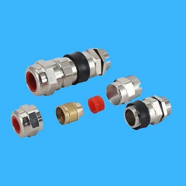
Being a professional instrumentation cable manufacturer over 20 years, we can offer you the cables in individual or overall shielded, armored or non-armored in single or mutiple cores,in paies or in triads for your different applications, together with Instrumentation gland and termination kit.
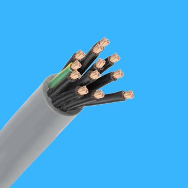
What is an Instrumentation Cable
Multiple conductor cables that convey low energy electrical signals are known as instrumentation cables. Instrumentation cables are used in a variety of industrial applications, including control & measurement, communication, data (analog/digital) and voice transmission, industrial signaling, and automation process control in the oil & gas, petrochemical, fertilizers, cement, and steel industries etc. the cables can be installed in cable tray or raceways, in conduit, direct burial or aerial application supported by a messenger wire.
Instrumentation Cable by UL Standard
UL Standard instrumentation cable types are XLPE Insulated PVC or LSZH jacketed, XLPE insulated, non-armored or steel wire armored instrumentation cable etc. If you need an instrumentation cable catalogue with UL standard, Please feel free to contact us.
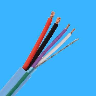
Copper Conductor Twisted in Pairs or Triads
XLPE Insulated
Non Shielded
PVC Outsheathed
Copper Conductor Twisted in Pairs or Triads
XLPE Insulated
Overall Shielded
PVC Outsheathed
Copper Conductor Twisted in Pairs or Triads
XLPE Insulated
Individual & Overall Shielded
PVC Outsheathed
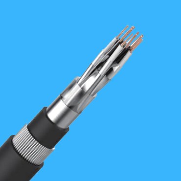
Copper Conductor Twisted in Pairs or Triads
XLPE Insulated
PVC Inner Sheath+SWA
PVC or LSZH Outsheathed
Copper Conductor Twisted in Pairs or Triads
XLPE Insulated,Overall Shielded
PVC Inner Sheath+SWA
PVC or LSZH Outsheathed
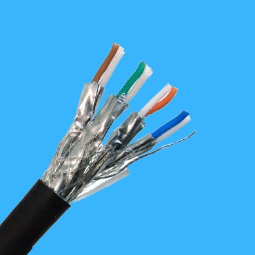
Copper Conductor Twisted in Pairs or Triads
XLPE Insulated, Individual & Overall Shielded
PVC Inner Sheath+SWA
PVC or LSZH Outsheathed
Instrumentation Cable by EN 50288-7 & BS 5308
EN & BS Standard Instrumentation Cable types are PVC, PE or XLPE Insulated, PVC or LSZH Sheathed in individual or overall screened and non-armored or steel wire armored instrumentaiton cable; if you would like to have our instrumentaiton cable specifcation, please consult it with engineers.
-
CU Conductor in Pairs or Triads
PVC, PE or XLPE Insulated
Overall Screened
PVC or LSZH Sheathed
-
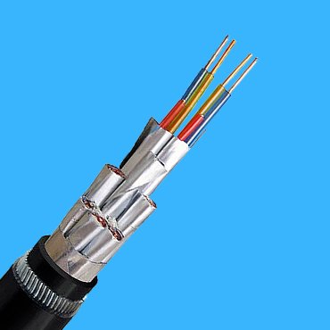
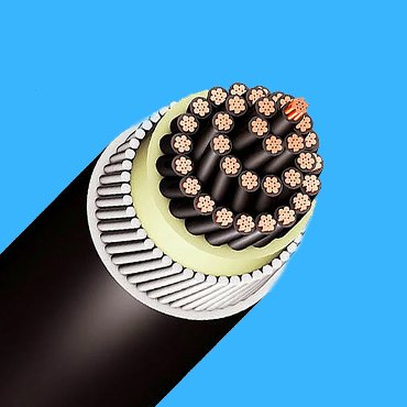
Overall Screened Armored Instrumentation Cable
CU Conductor in Pairs or Triads
PVC, PE or XLPE Insulated
Overall Screened, Inner Sheath+ SWA
PVC or LSZH Sheathed
-
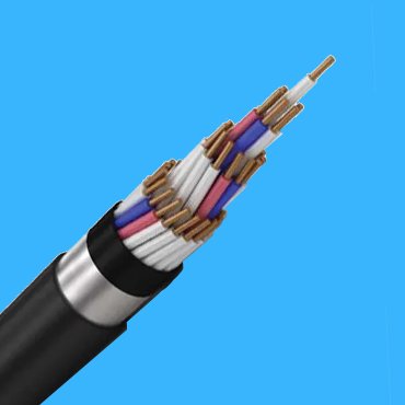
 Individual & Overall Screened Instrumentation Cable
CU Conductor in Pairs or Triads
PVC, PE or XLPE Insulated
Individual & Overall Screened
PVC or LSZH Sheathed
-
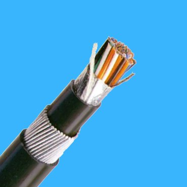
Double Shielded Instrumentation Cable
CU Conductor in Pairs or Triads
PVC, PE or XLPE Insulated
Indivual & Overall Screened, Inner Sheath+ SWA
PVC or LSZH Sheathed
-
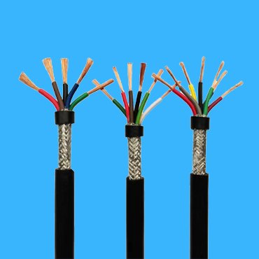
Instrumentation Cable
CU Conductor in Pairs or Triads
PVC, PE or XLPE Insulated
CU Wire Braid Screened
PVC or LSZH Sheathed
Instrumentation Cable by NF M 87-202 & PAS 5308
For NF M 87-202 & PAS 5308 standard instrumentation cable, in some special applications, the cable need to add a lead sheath. Please check it with our technial expertise for a proper type instrumentation cable to fit your need.
-
CU Conductor in Pairs or Triads
PVC Insulated
Overall Screened
PVC or LSZH Sheathed
-
EGFA
CU Conductor in Pairs or Triads
PVC Insulated
Overall Screened, Inner Sheath+ STA
PVC or LSZH Sheathed
-
CU Conductor in Pairs or Triads
PVC Insulated Overall Screened, Inner Sheath+ Lead Sheath + STA
PVC or LSZH Sheathed
-
 EIFA
EIFACU Conductor in Pairs or Triads
PVC Insulated
Individual & Overall Screened+Inner Sheath+STA
PVC or LSZH Sheathed
-
EIPF
CU Conductor in Pairs or Triads
PVC Insulated
Individual & Overall Screened, Inner Sheath+ Lead Sheath + STA
PVC or LSZH Sheathed
-
PAS 5308 Instrumentation Cable
CU Conductor in Pairs or Triads
PE or PVC Insulated
Overall Screened
PVC or LSZH Sheathed
-
CU Conductor in Pairs or Triads
PE or PVC Insulated
Individual & Overall Screened
PVC or LSZH Sheathed
-
CU Conductor in Pairs or Triads
PE or PVC Insulated
Overall Screened+Inner Sheath+SWA
PVC or LSZH Sheathed
-
CU Conductor in Pairs or Triads
PE or PVC Insulated
Individual & Overall Screened+Inner Sheath+SWA
PVC or LSZH Sheathed
-
CU Conductor in Pairs or Triads
PE or PVC Insulated
Overall Screened+Inner Sheath+Lead Sheath+SWA
PVC or LSZH Sheathed
Product Feature Box


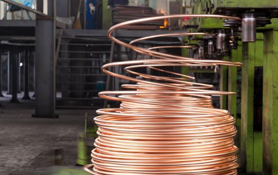
High Purity Copper Conductor
The High Purity Copper Conductor used in our instrumentation cable is guaranteed to provide the highest quality possible.
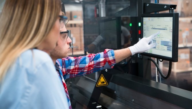
Stringent Quality Control & Testing Management
Stringent Quality Control & Testing Management would be another measure to further guarantee the quality and reliability of our instrumentation cable, ensuring that it meets the highest standards of quality and performance.
Tailored Design & Fabrication for your Instrumentation Cable
We are committted to providing customized design and fabrication services for your instrumentation cable needs. Our experienced & dedicated engineers will work with you to create a tailored solution that is tailored to meet your exact requirements for Instrumentation cable. We use the latest technology and materials to ensure the highest quality of the instrumentation cable and provide you with a complete and satisfactory result.

Related Product
Installation Guide for Instrumentation Cable
- Selection & Installation of Cable Tray
- Installation of cable conduit
- Installation of Instrumentation Cable 3.1 The cable should be laid in a centralized manner along the shortest path, horizontally and vertically, neatly and aesthetically pleasing, and should not cross. The cable should not be laid in a position that affects operation or hinders equipment and pipeline maintenance; The cable should not be laid above high-temperature equipment or pipelines, nor should it be laid below corrosive pipelines or equipment.3.2 The cable should not be laid in a location that is prone to mechanical damage, corrosive substance emissions, humidity, and interference from strong magnetic and electrostatic fields. When unavoidable, protective or shielding measures should be taken.When the ambient temperature around the line exceeds 65 ℃, insulation measures should be taken. When there is a fire source near the line, fire prevention measures should be taken.The distance between the insulation layer of the pipeline and the insulated equipment should be greater than 200mm, and the distance between the insulation layer and other equipment and pipeline surfaces should be greater than 150mm.3.5 When the instrumentation cable enters the room from outside, waterproof and blocking measures should be taken. When instrumentation cable enters the panel, cabinet, or box, it is advisable to enter from the bottom and there should be waterproof and sealing measures.3.6 After the instrumentation cable is laid, a continuity test and labeling should be conducted, and the insulation resistance of the cable and wire should be measured, and the insulation resistance measurement record should be filled out. The measurement of insulation resistance should be carried out before the wiring of instrument equipment and components, otherwise the connected instrument equipment and components must be disconnected. The insulation resistance measurement of cables includes measuring the direction of the cable core, the insulation resistance between the cable core and the outer protective layer, and the insulation layer.3.7 When the ambiebt temperature is lower than 0 ℃, it is not allowed to installed all PVC/PE or XLPE insulatted power cables, while it is not allowed for rubber insulated cables when it is less than -15 ℃.3.8 Cable laying should be arranged reasonably and not crossed to prevent friction between cables or between cables and other hard objects.3.9 Instrumentation Cables with different signals, voltage levels, and intrinsically safe explosion-proof systems in the same cable tray should be isolated with metal partitions and classified and laid in zones according to the design documents.
3.10 Instrumentation Cables should be arranged neatly in cable trays or trays. When laying in vertical cable trays, brackets should be used to fix them and ensure moderate tightness. Allowance shall be reserved for the turning, both ends, expansion joint, thermal compensation section, shock prone and other parts of the cable. The bending radius of multi-core control cables should not be less than 10 times the outer diameter, and the minimum bending radius of armored cables should not be less than 10 times the outer diameter of their protective tubes.
3.11 When multiple cable trays are laid vertically in layers, the cables should be arranged in layers from top to bottom in order of instrumentation cables, safety interlocking lines, AC and DC power supply lines.
3.12 There should be no intermediate joint in the cable. If it is unavoidable, it should be connected inside the junction box or junction box. The core wire of the intermediate joint should be wrapped with the same polarity, crimped, and sealed with thermoplastic pipe, wrapped with insulation tape, hung with a signboard, and marked with its position in the concealed record. When welding is used, non corrosive welding flux should be used. Special connectors should be used for coaxial cables and high-frequency cables.
3.13 The clear distance between the signal cable laid in the open and electrical equipment with strong electric and magnetic fields should be greater than 1.5m; When shielded cables pass through metal protective pipes and are laid in cable trays, they should be greater than 0.8m.
3.14 When intrinsic safety lines and non intrinsic safety lines are laid in the same tray or cable trench, the spacing should be greater than 50mm.
3.15 The instrumentation cable laying of the integrated control system and digital communication lines should be carried out in accordance with the requirements of the design documents and product technical documents, and cables of different voltage levels should not be laid in the same cable tray. If unavoidable, metal plates should be used for isolation; Shielded cables should be used for signal lines, and network channel cables with dual redundant structures should be separately isolated and laid.
3.16 When instrumentation cables intersect with power cables, they should be at right angles; When laying in parallel, the distance between the two should comply with the provisions of the design documents.
3.17 The spacing between network communication cables and power supply lines should comply with the requirements of the design documents to prevent interference.