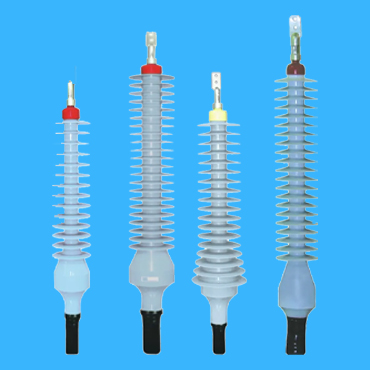
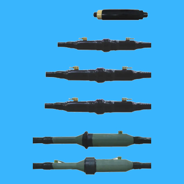
Due to different voltage level, it has several types of power cable termination; in this post, we are only focusing on 35 kV medium voltage power cable termination and how to make it, which will include the following contents.
- what is a power cable termination and its main features
- standard reference for power cable termination
- grounding issues for power cable termination
- steps for making this power cable termination


what is a power cable termination and its main features
Power cable termination is a component that connects the power cable to other electrical equipments; it has two main types, cold shrink cable termination and heat shrink cable termination; while power cable middle joint is a component that connects two power cables together; The cable termination kit and intermediate cable joint are collectively referred to as cable accessories.
these two cable accessories should be able to operate safely for a long time and have the same service life as the power cable itself. Good cable accessories should have the following performance:
1. The wire core is well connected
Mainly, the connection resistance is small and stable, able to withstand the impact of fault current; After long-term operation, the contact resistance should not be greater than 1.2 times the length resistance of the cable core body; It should have certain mechanical strength, vibration resistance, and corrosion resistance; this
It should also have a small size and be easy to install on site.
2. Good insulation performance
The insulation performance of power cable termination should not be lower than that of the power cable itself, and the insulation materials used should be dielectric loss should be low, and the structure should be able to withstand sudden changes in the electric field in the power cable termination kit. it is good at handling and have measures to change the distribution of the electric field.
standard reference for power cable termination
● IEC62067 “Rated voltage above 150kV (Um=170kV) to
Power cable systems for 500kV (Um=550kV) extruded insulated power cables and their accessories – Test methods and requirements
IEC60840 “Rated voltage above 30kV (Um=36kV) to 150kV
Test methods and requirements for extruded insulated power cables and their accessories (Um=170kV)
IEC60859 “Cable Connection Devices for Gas Insulated Metal Enclosed Switches with Rated Voltages of 72.5kV and Above”
● IEC60502 “Rated voltage above 1kV (Um=1.2kV) to 30kV
(Um=36kV) extruded insulated power cables and their accessories
IEC60055 “Paper insulated metal sheaths (with copper or aluminum conductors, but excluding compressed air and oil filled cables) with rated voltages of 18/30kV and below” Part 1 “Tests on cables and accessories” Chapter 7: Type tests on accessories
IEC61442 “Rated voltage from 6kV (Um=7.2kV) to 30kV
Test methods for accessories of power cables (Um=36kV)
Grounding issues for power cable termination
10 kV power cables with copper shielding or steel wire armored generally require grounding. What is the difference between grounding at both ends and grounding at one end? Can the steel armor and copper shielding layer be welded together when making this power cable termination? Can the steel armor and copper shielding layer be welded together when making the middle joint of the power cable?
35KV high-voltage cables are mostly in a single core. When a single core cable is powered on for operation, an induced voltage will be formed at the shielding layer. If the shields at both ends are grounded at the same time, a circuit will be formed between the shielding layer and the ground, which will generate induced current. This will cause the shielding layer of the cable to heat up, consume a large amount of electrical energy, and affect the normal operation of the line. To avoid this phenomenon, one end is usually grounded, When the line is very long, methods such as midpoint grounding and cross connection can also be used.
When making this power cable termination, the steel armor and copper shielding layer are welded and grounded separately to facilitate the inspection of the internal protective layer of the power cable. When inspecting the cable protective layer, a voltage is applied between the steel armor and copper shielding. If it can withstand a certain voltage, it proves that the internal protective layer is intact and undamaged. If there are no such requirements, there is no need to test the inner protective layer of the cable, and the steel armor and copper shielding layer can also be connected to ground together. (We advocate grounding after separate leads)
Why do high-voltage single core cross-linked polyethylene insulated power cables require special grounding methods?
The electrical safety regulations stipulate that all non charged metal shells of electrical equipment must be grounded, so the aluminum cladding or metal shielding layer of the cable must be grounded. Usually, cables with voltage levels below 35kV are grounded at both ends. This is because most of these cables are three core cables. In normal operation, the total current flowing through the three cores is zero, and there is basically no magnetic flux outside the aluminum or metal shielding layer. Therefore, there is basically no induced voltage at both ends of the aluminum or metal shielding layer, so there will be no induced current flowing through the aluminum or metal shielding layer after grounding at both ends. However, when the voltage exceeds 35kV, most single core cables are used. The relationship between the core of a single core cable and the metal shield can be seen as the primary winding of a distribution transformer. When a single core cable core passes through an electric current, there will be a magnetic field wire cross-linked with aluminum or metal shielding layer, causing induced voltage to appear at both ends.
The magnitude of the induced voltage is proportional to the length of the cable line and the current flowing through the conductor. When the cable is very long, the induced voltage on the sheath can be combined to endanger personal safety. In the event of a short circuit fault, operating overvoltage, or lightning impact on the line, a high induced voltage will form on the shield, and may even break through the insulation of the sheath.
At this point, if the two ends of the aluminum package or metal shielding layer are still interconnected and grounded, there will be a large circulating current in the aluminum package or metal shielding layer, which can reach 50% -95% of the core current, forming losses and causing the aluminum package or metal shielding layer to heat up. This not only wastes a lot of electricity, but also reduces the current carrying capacity of the power cable and accelerates the insulation aging of the power cable. Therefore, single core cables should not be grounded at both ends. Only in individual cases (such as short cables or light load operation) can the aluminum cladding or metal shielding layer be interconnected and grounded at both ends.
It can be seen that there are several grounding methods for high-voltage cables:
1. One end of the protective layer is directly grounded, and the other end is protected and grounded through the protective layer – methods can be adopted;
2. The midpoint of the protective layer is directly grounded, and the shielding at both ends is grounded through the protective layer – commonly used method;
3. Cross interconnection of protective layers – commonly used methods;
4. Cable transposition and metal sheath cross interconnection – the most effective grounding method;
5. Grounding at both ends of the sheath – not commonly used, only suitable for extremely short cables and small load cable lines.
Steps for making this power cable termination
1) Peel off the outer sheath
To prevent the steel armor from loosening, the outer protective layer should be peeled off one to one circle on the inner side of the steel armor cutting point (left on the outer side), and a clamp should be made. The steel armor should be tied tightly with copper wire and the grounding wire of the steel armor should be welded properly. Finally, peel off the outer sheath.
2) Saw steel armor. After the previous step is completed, cut a circular deep mark along the edge of the clip (copper wire edge if there is no clip) along the direction of the steel armor wrapping. (Do not cut off the second layer of steel armor, otherwise it will damage the cable), use a flat screwdriver to pry it up (the steel armor edge is broken), then use pliers to pull it down and loosen the steel armor, remove the steel armor strip, and handle the burrs at the sawn off point. The entire process should be wrapped tightly in the direction of the steel armor, and the steel armor on the cable should not be loosened.
3) Peel off the inner insulation layer and pay attention to protecting the color identification line to ensure the insulation between the copper shielding layer and the steel armor.
4) Welding shielding layer grounding wire
Remove the oxide from the copper shielding layer copper strip on the outer side of the inner protective layer and apply soldering tin. Bind the grounding flat copper wire of the accessory (divided into three strands) tightly on the copper shielding layer coated with solder, handle the head of the binding wire, and then solder it to the copper shielding layer to solder the wire head.
5) Copper shielding layer treatment
Mark the phase color at the fork of the cable core wire, correctly measure the position of the cut off copper shielding layer according to the cable attachment manual, solder it firmly (to prevent the copper shielding layer from loosening), tie it tightly with copper wire on the inside of the cut off area, and make a shallow mark along the copper wire along the tightening direction with a knife (note that the semiconductor layer cannot be cut!). Slowly tear off the copper shielding tape, and finally remove the copper wire along the tightening direction of the copper tape.
6) Peel off semi conductive layer
The semi conductive layer fracture is located 10mm away from the copper strip fracture, and a circle of tape is wrapped on the inner side of the fracture for marking. At the predetermined cutting point of the semi conductive layer (outer side of the tape), use a knife to scratch the ring mark, and make two vertical marks from the ring mark to the end, with a distance of about. Tear off the conductive layer from the end to the ring mark direction (note that the semi conductive layer on the inner side of the ring mark cannot be pulled up!). When using a knife to scratch, the insulation layer should not be damaged, and the fracture of the semi conductive layer should be neat. Check the surface of the main insulation layer for knife marks and residual semi conductive materials, and clean it if any.
7) Clean the surface of the main insulation layer
Use a lint free cloth or cleaning paper soaked in cleaning agent to clean the dirt on the main insulation surface. Only from the insulation end to the semiconductor layer is allowed during cleaning, and repeated wiping is not allowed to avoid bringing semi conductive substances onto the surface of the main insulation layer.
PowerTel and his associated factories are able to provide you a full range of 35 kV medium voltage power cable and its power cable termination, as well as its professional guide line on how to make this power cable termination, thus to help you have a reliable and safe connection of your power cables and electrical equipments.
