Your Best Power Transformer Manufacturer in China since 1985
Being a leading power transformer manufacturer since 1985, over 40 years manufacturing experience, our power transformers are of,
- High Reliability and Safety
- Minimal Loss and Minimal Noise
- Exquisite Craftsmanship for a high quality products
- A higher performance in terms of safety, humanization and intelligence etc
What is a Power Tranformer
Power Transformer,is an electrical equipment that uses the principle of electromagnetic induction to change voltage in an electrical system. Main functions include voltage conversion, current conversion, impedance conversion, isolation, voltage stabilization etc. it has step-up or step-down transformer, fully sealed transformer, furnace transformer, rectifier transformer, reactor, anti-interference transformer, lightning protection transformer etc.
PowerTel & its associated factory has over 40 years experience in researching, designing and manufacturing a wide range of power transformers used in power transmission & distribution lines, in substation, solar & wind farms, and in some commercial & industrial buildings. Please consult it with our expert engineers to give you a tailored design to fit your custom need for your project.
High Voltage Power Transformer
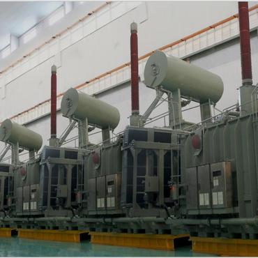
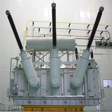
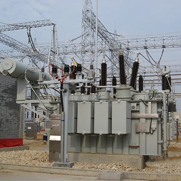
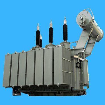
It mainly include oil-immersed power transformer or oil filled power transformer voltage level ranged from 110 kV to 500 kV, and rated capacity from 5 MVA to 1,500 MVA.
Rated capacity: from 240 to 1,500 MVA
Connection Symbol: YNd11
Rated capacity: from 150 to 1,000 MVA
Connection Symbol: YNd11
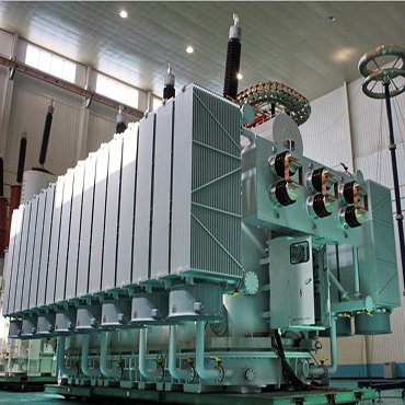
Rated capacity: from 50 to 1,000 MVA
Connection Symbol: YNd11
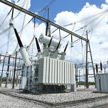
Rated capacity: from 30 to 600 MVA
Connection Symbol: YNd11
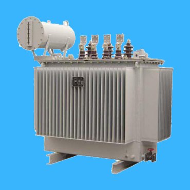
Medium Voltage Power Transformer
Product Feature Box


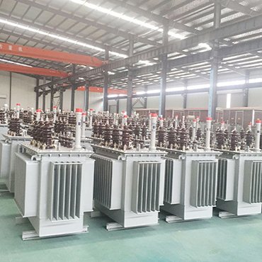
Manufacturing Facilities
By integrating our advanced manufacturing capabilities with up-to-date technology for power transformers, we are able to provide tailored solutions for a variety of applications and locations, up to 500 kV and 1,500 MVA.


Guaranteed Quality
Our team of expert engineers will oversee your projects from the initial design phase, monitoring production to routine & type testing and final commissioning, and even after handing it over.
Lifecycle Technical Support
For more than 50 years, our highly skilled service teams have been fully trained to ship, install, and manage power transformers, from the erection, commissioning, testing to final energizing on site; Maintenance and Repairing or Replacement work will go through on-line at 24/7 and on-site inspection & testing if it is necessary.

Related Product
What is a Power Transformer
It is a core electrical equipment for a power transmission & distribution project and its associated electrical substations. A power transformer is a static electrical device that utilizes the principle of electromagnetic induction to convert one type of alternating current into another or several types of alternating current with the same frequency and different sizes, playing a role in transmitting electrical energy and changing voltage rate.
Basic Principle of a Power Transformer
When the primary winding of a power transformer is connected to an AC power source, alternating current will flow through the winding and generate alternating magnetic flux in the core. This alternating magnetic flux is interconnected with the primary and secondary windings, and alternating induced electromotive force will be induced in them. The secondary winding has induced electromotive force, and if connected to the load, it can supply power to the load, transmit electrical energy, and achieve energy transfer from the primary side to the secondary side.
Classification of a Power Transformer
According to the number of phases: single-phase transformer, three-phase transformer
Depending on the number of windings
Double winding transformer, three winding transformer, auto transformer
According to different cooling modes: oil immersed self cooling transformer, oil immersed air-cooled transformer, oil immersed water-cooled transformer, forced oil circulation air-cooled transformer, dry-type transformer;
According to different purposes:
Power transformers (step-up transformers, step-down transformers, distribution transformers, etc.
Special transformers, like furnace transformer, rectifier transformer, welding transformer etc.
Instrument transformers, like voltage transformers and current transformers,and high-voltage transformers for testing.
Main technical parameters of a power transformer
Rated value of a power transformer
The maximum load power when operating under rated conditions. Generally: Small transformers with a capacity of no more than 630kVA; 800-6300kVA is a medium-sized transformer; 8000-63000kVA is a large transformer; over 90000kVA is a super large transformer.
Divided into primary and secondary voltages. Generally, the voltage levels are 400V, 3kV, 6kV, 10kV, 35kV, 66kV, 110kV, 220kV, 330kV, and 500kV. for tapping ± 5%.
The rated current I1N/I2N refers to the current that a transformer is allowed to pass through for a long time, and the unit of (line current) is A. The rated current can be calculated from the rated capacity and rated voltage.
The rated frequency f of industrial AC power is 50Hz or 50Hz.
No-load test:
Measure the voltage transformation ratio k, no-load current I0, and no-load loss p0
The no-load loss of transformers is mainly iron loss, which is the power loss caused by excitation current and can be divided into eddy current and hysteresis loss, roughly proportional to the square of the voltage.
The no-load current I0 is basically the excitation current of the transformer, which is generally 2-8% for small and medium-sized transformers, and less than 1% for large ones.
Short circuit test:
Measure the short-circuit voltage Uk and short-circuit power (i.e. short-circuit loss)
The main short-circuit load loss is copper loss (referred to as aluminum loss in aluminum wire transformers).
Copper loss refers to the ohmic resistance loss caused by winding current, which is roughly proportional to the square of the current.
Impedance voltage:
The percentage of the ratio between the actual value of short-circuit voltage Uk and the rated voltage U1N is called impedance voltage uk.
uk=(Uk/U1N)*100%
The impedance voltage uk is an important parameter of a transformer, and its size mainly depends on the design size of the transformer. The selection of uk involves factors such as transformer cost/efficiency/voltage stability/short-circuit current size.
During normal operation, it is hoped that the uk is smaller, so that the terminal voltage fluctuates less with the load. But when a sudden short circuit occurs, I hope the uk is larger to reduce the short-circuit current.
What components are there for a power transformer
AL or CU windings & iron core would be two most important parts in a power transformer. The two constitute the core of the transformer, which is the electromagnetic part. In addition to the electromagnetic part, there are also accessories such as oil tanks, oil storage cabinets, tap changers, safety airways, gas relays, insulation sleeves, and oil purifiers. Transformer oil is a kind of mineral oil with good insulation performance. Main functions of transformer oil: 1 it plays an insulating role between transformer winding and winding, winding and iron core and oil tank. 2 When heated, transformer oil will generate convection, which will heat the transformer core and winding. 3 When a discharge fault occurs inside the transformer, it has an arc extinguishing effect.The oil tank has many heat dissipation pipes to increase the heat dissipation area. In order to speed up heat dissipation, large transformers use internal oil pumps to force oil circulation, and use transformer fans to blow outside or use tap water to flush the transformer oil tank. These are all cooling devices for transformers.
Gas Relay for a Power Transformer
When there are inter turn short circuits, insulation damage, poor contact, and multiple grounding faults in the transformer, a large amount of heat energy will be generated, causing the oil to decompose into combustible gases and flow towards the oil storage tank. When the flow rate exceeds the set value of the gas relay, the baffle of the gas relay is impacted, causing the relay to trip, thereby avoiding the expansion of the accident. This situation is usually referred to as heavy gas protection action. When the gas rises along the oil surface and accumulates in the gas relay for more than 30ml, the signal contact of the gas relay can also be connected, giving an alarm, and light gas protection occurs. By analyzing transformer faults and identifying the causes of gas relay action, the nature and location of the faults in the transformer can be determined based on different reasons, and effective repairs can be carried out to restore normal operation as soon as possible.
Installation Guide for a Power Transformer
Conduct a visual inspection of the power transformer before installation. Verify whether the product model, capacity, voltage, connection group, short-circuit impedance, etc. of the transformer match the design.
Conduct a visual inspection of the transformer before installation. Check if the transformer is damaged during transportation; Whether there are signs of oil leakage and whether the oil level and color are normal; Whether the accessories are damaged and displaced; Whether the fasteners are loose; Is there any damage to the insulation.
Routine Inspections for a Power Transformer
(1) Check & confirm that if the oil temperature gauge is in allowable range or not. Due to the different load sizes, cooling conditions, and seasons of each transformer, the operating transformer should not only be based on the upper oil temperature not exceeding 85 °C, but should also be compared with the previous oil temperature based on past operating experience and in the above situations. If the oil temperature suddenly increases, check whether the cooling device is normal and whether the oil circulation is damaged.
(2) Check the oil quality, it should be transparent and slightly yellow. The oil level should meet the standard line of the surrounding temperature. If the oil level is too low, the transformer should be checked for oil leakage, etc. If the oil level is too high, the use of the cooling device should be checked for internal faults.
(3) The sound of the transformer should be normal. During normal operation, there is generally a uniform buzzing electromagnetic sound. If there is a change in the sound, it should be carefully checked and promptly reported to the duty dispatcher, and the maintenance unit should handle it.
(4) The casing should be checked for cleanliness, cracks, and discharge marks, and the cooling device should be functioning properly.
(5) Special inspections should be conducted when the weather changes. When there is a strong wind, check if the leads swing violently, and there should be no debris at the top cover and bushing leads of the transformer; During heavy snowfall, all contacts should not immediately melt or discharge after snowfall; On foggy days, whether there are sparks or discharges in various parts, etc.
The newly installed power transformer operates at no load for 24 hours before being loaded; The high-voltage side voltage shall not exceed ± 5%; The maximum unbalanced current of low voltage shall not exceed 25%; Due to the use of Class A insulation in transformers, their maximum operating temperature is 105 °C. So the temperature rise of the winding should not exceed 65 °C, the upper oil temperature should not exceed 85 °C, and the maximum temperature should not exceed 95 °C; Transformers should not be overloaded for a long time, but overload is allowed under special circumstances, but the overload time must be adapted to the temperature and overload amount.
Protections for a Power Transformer
- Lightning protection
Install lightning arresters to protect against immersion waves along the line;
- a) While installing zinc oxide lightning arresters on the high-voltage side, zinc oxide lightning arresters that meet the requirements should also be installed on the low-voltage side according to regulations; b) The grounding terminals of the high and low voltage side lightning arresters, the neutral point on the low voltage side, and the distribution transformer casing must be short circuited nearby before being centrally connected to the grounding grid;
- c) The high-voltage side lightning arrester should be installed on the load side of the drop type fuse.
- Fuse protection:
1 The main function of the high-voltage side fuse of the transformer is to protect the transformer and quickly fuse when there is an internal short circuit or a high-voltage lead short circuit in the transformer.
Principle of fuse selection: For transformers with a capacity of 100kVA or less, the fuse should be selected based on 2-3 times the rated current; When the transformer capacity is above 100kVA, the fuse should be selected according to 1.5~2 times the rated current.
2 the fuse used in primary side of a power transformer is for short circuit protection and in secondary side is for overload protection. The size of the fuse is selected based on the secondary load current or rated secondary current of the transformer.
- Relay protection
It is generally referred to as a relay protection device.
Handling Guide for a power transformer when there is a fault
1.handling guide when Bushingsfailure for a Power ransformer
The common faults would be like explosion, flashover, and oil leakage, and the reasons should be Poor sealing and poor insulation due to moisture or some other issues.
Iron Core failure of a Power Transformer
It may also cause local short circuits in the iron core laminations, generate eddy current overheating, cause damage to the insulation layer between the laminations, increase the no-load loss of the transformer, and deteriorate the insulation oil.
Gas protection fault for a Power Transformer
Finally, When a power transformer trips automatically, it is necessary to investigate the protection action and conduct external inspections. After inspection, if it is not an internal fault but is caused by external faults (transient faults) or personnel malfunctions, power transmission can be put into operation without internal inspection. If differential protection is activated, all equipment within the protection range should be inspected.

